
Eureka
For R&D, Eureka makes reading and utilizing patents & technical documents easy.
Eureka AIR
Designed for self-driven R&D workflows. Generate viable solutions, solve complex R&D challenges, empower your innovation with AI.

Eureka Materials
Designed for material experts only. Revolutionize your material R&D, from search, analyze, to developing new materials.

TechResearch
Generate reliable direction feasibility study reports for your R&D in just a few steps.

TechSeek
Discover and master advanced knowledge NOW. Basics, ideas, possibilities, all at once.

TechMind
As an expert in R&D Theories, TechMind can generates customized viable solutions instantly.

TechRisk
Analyze your overall solution with one click, know your potential R&D risks in advance.

TechMonitor
Get weekly tech updates, stay abreast of the latest tech innovations and key insights.
Power receiver, non-contact power transmission system, and method of controlling received-power voltage
- Summary
- Abstract
- Description
- Claims
- Application Information
AI Technical Summary
Benefits of technology
Problems solved by technology
Method used
Image

Examples
first embodiment
1. First Embodiment
[0032](Background of Disclosure)
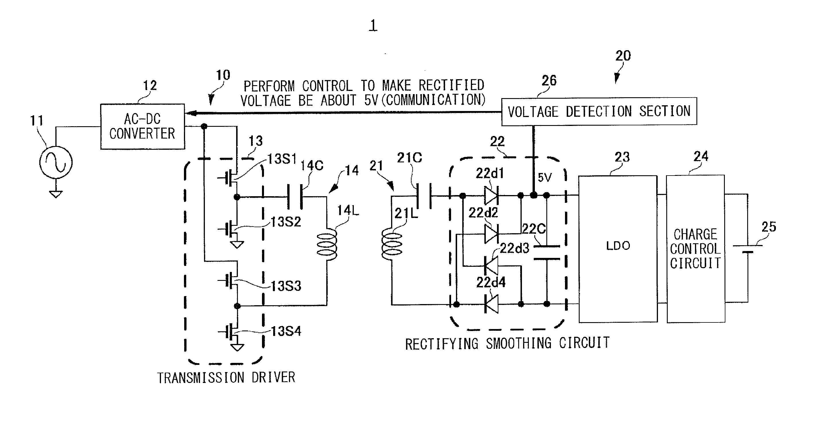
[0033]FIG. 1 is a block diagram illustrating a circuit configuration example of a non-contact power transmission system using LDO that is a series regulator. A non-contact power transmission system 1 illustrated in FIG. 1 includes a power transmitter 10 (a primary-side unit) and a power receiver 20 (a secondary-side unit), and may transmit (feed) power from the power transmitter 10 to the power receiver 20 by an electromagnetic induction method in a non-contact manner.
[0034]The power transmitter 10 may include an AC power source 11, an AC-DC converter 12, a transmission driver 13, and a resonance circuit 14, for example. The AC-DC converter 12 converts an AC signal generated by the AC power source 11 into a DC signal, and supplies the DC signal to the transmission driver 13. The transmission driver 13 converts the DC signal received from the AC-DC converter 12 into an AC signal while performing voltage conversion, and supplies the A...
second embodiment
2. Second Embodiment
[0093]The target voltage value in the power receiver 20B (FIG. 3) may be set so that the power transmission efficiency (inter-coil efficiency) between the primary-side coil and the secondary-side coil that are magnetically coupled is a maximum. Hereinafter, as a second embodiment, received-power voltage control in the case where the target voltage value is determined so that the inter-coil efficiency (hereinafter, referred to as “efficiency”) is a maximum.
[0094]The total loss generated on the primary-side coil 14L and the secondary-side coil 21L is determined from a load resistance value in anticipation of a load from the secondary-side coil 21L to the power receiver 20B. To maximize the efficiency and to minimize the total heat generated by the primary-side coil 14L and the secondary-side coil 21L, the load may be adjusted to a load resistance value RLopt (so-called optimum load resistance value) having a minimum loss. When a resonance frequency of the resonance...
third embodiment
3. Third Embodiment
[0104]FIG. 7 is a block diagram illustrating a circuit configuration example of a non-contact power transmission system according to a third embodiment of the disclosure. A non-contact power transmission system 1C illustrated in FIG. 7 includes the power transmitter 10B, and a power receiver 20C that is configured by further providing a parameter measurement section 33 to the power receiver 20B illustrated in FIG. 3. The parameter measurement section 33 includes a circuit for measuring necessary parameters.
[0105]The parameter measurement section 33 measures the output current of the rectifying section 22A and the output voltage of the regulator 28. For example, the parameter measurement section 33 may measure the resistance value of the secondary-side coil 21L in real time. Moreover, the parameter measurement section 33 may measure a potential of a first terminal side (V1) and a potential of a second terminal side (V2) of the resonance capacitor 21C1 to measure a ...
PUM
 Abstract
Description
Claims
Application Information
 - R&D Engineer
- R&D Manager
- IP Professional
- Industry Leading Data Capabilities
- Powerful AI technology
- Patent DNA Extraction
Browse by: Latest US Patents, China's latest patents, Technical Efficacy Thesaurus, Application Domain, Technology Topic, Popular Technical Reports.
© 2024 PatSnap. All rights reserved.Legal|Privacy policy|Modern Slavery Act Transparency Statement|Sitemap|About US| Contact US: help@patsnap.com