Systems and Methods for Power Payment Based on Proximity

a technology of proximity and power payment, applied in the direction of transformers, inductances, transportation and packaging, etc., can solve the problems of inoperable electronic devices, burden on users, and tedious activities

Inactive Publication Date: 2015-11-26
ENERGOUS CORPORATION
View PDF2 Cites 238 Cited by
  • Summary
  • Abstract
  • Description
  • Claims
  • Application Information

AI Technical Summary

Benefits of technology

[0008]The presented methods may include the association of power receivers with customers to keep track of the power consumption of customers' electronic devices. The system may allow the computation of bills based on power consumption.

Problems solved by technology

Such an activity may be tedious and may represent a burden to users.
However, such an activity may in some cases render electronic devices inoperable during charging.

Method used


Image

  • Systems and Methods for Power Payment Based on Proximity
  • Systems and Methods for Power Payment Based on Proximity
  • Systems and Methods for Power Payment Based on Proximity

Examples


examples

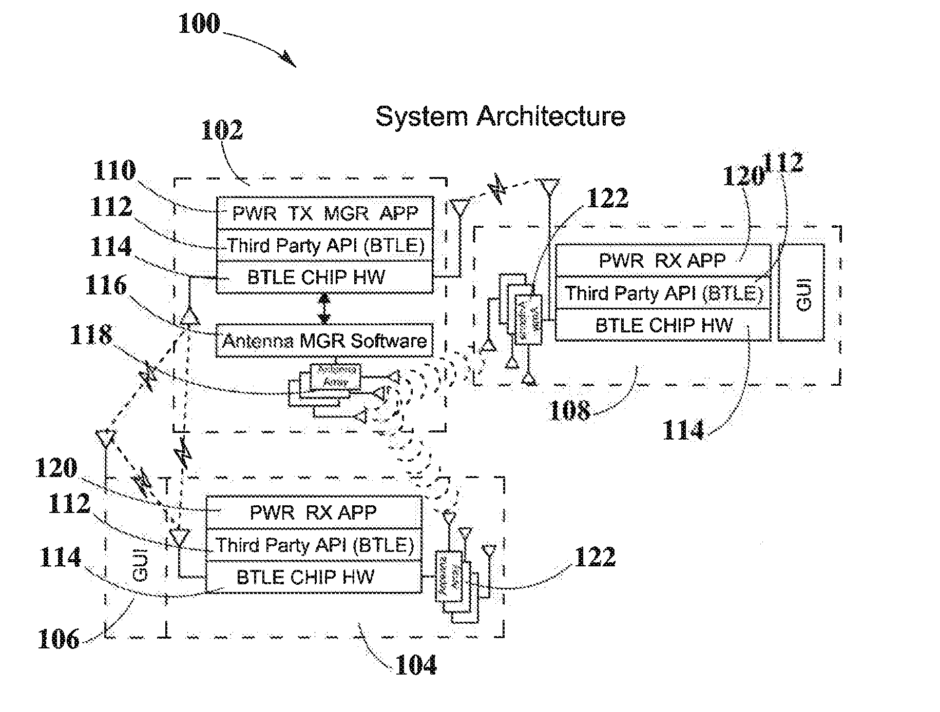
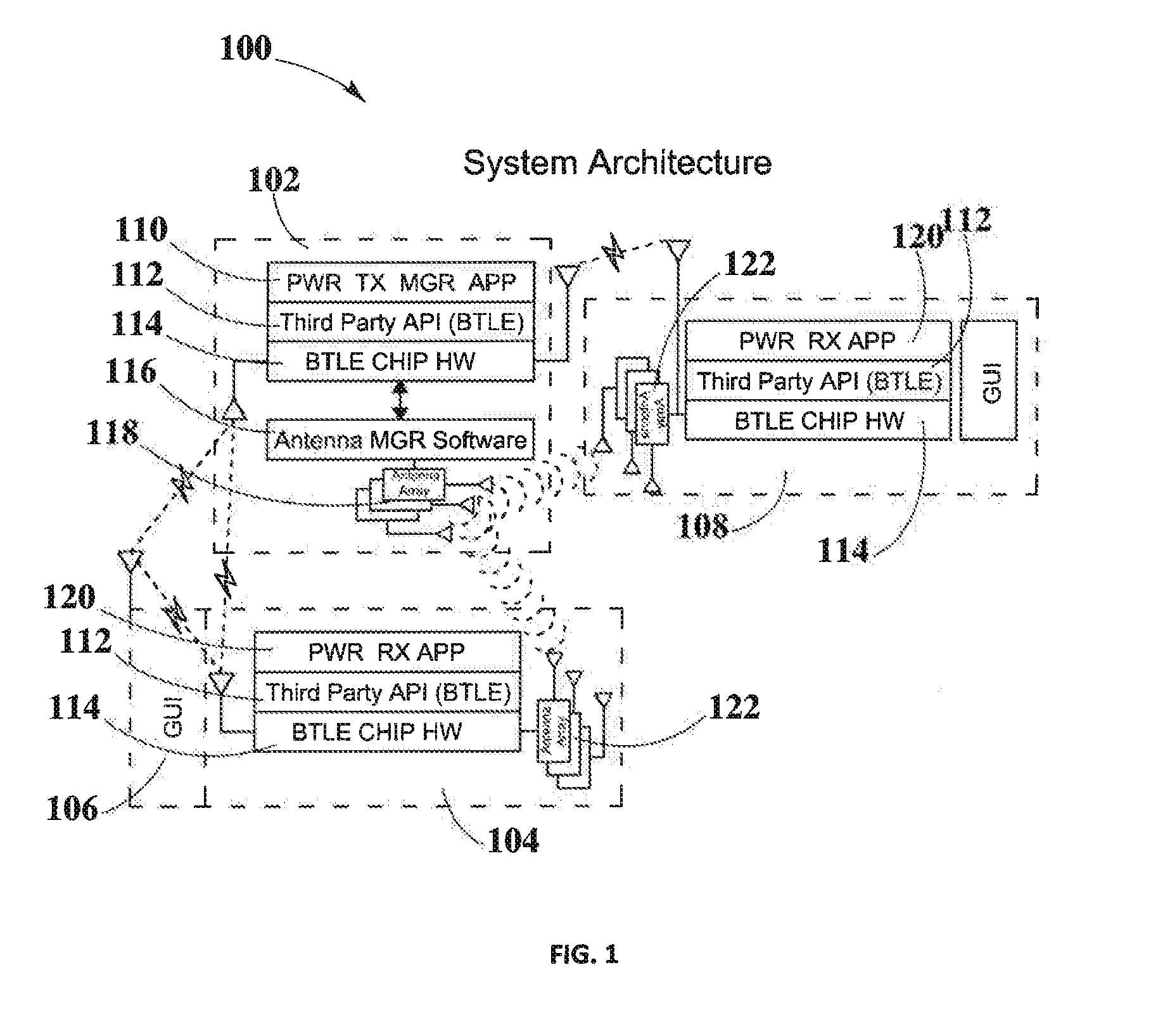
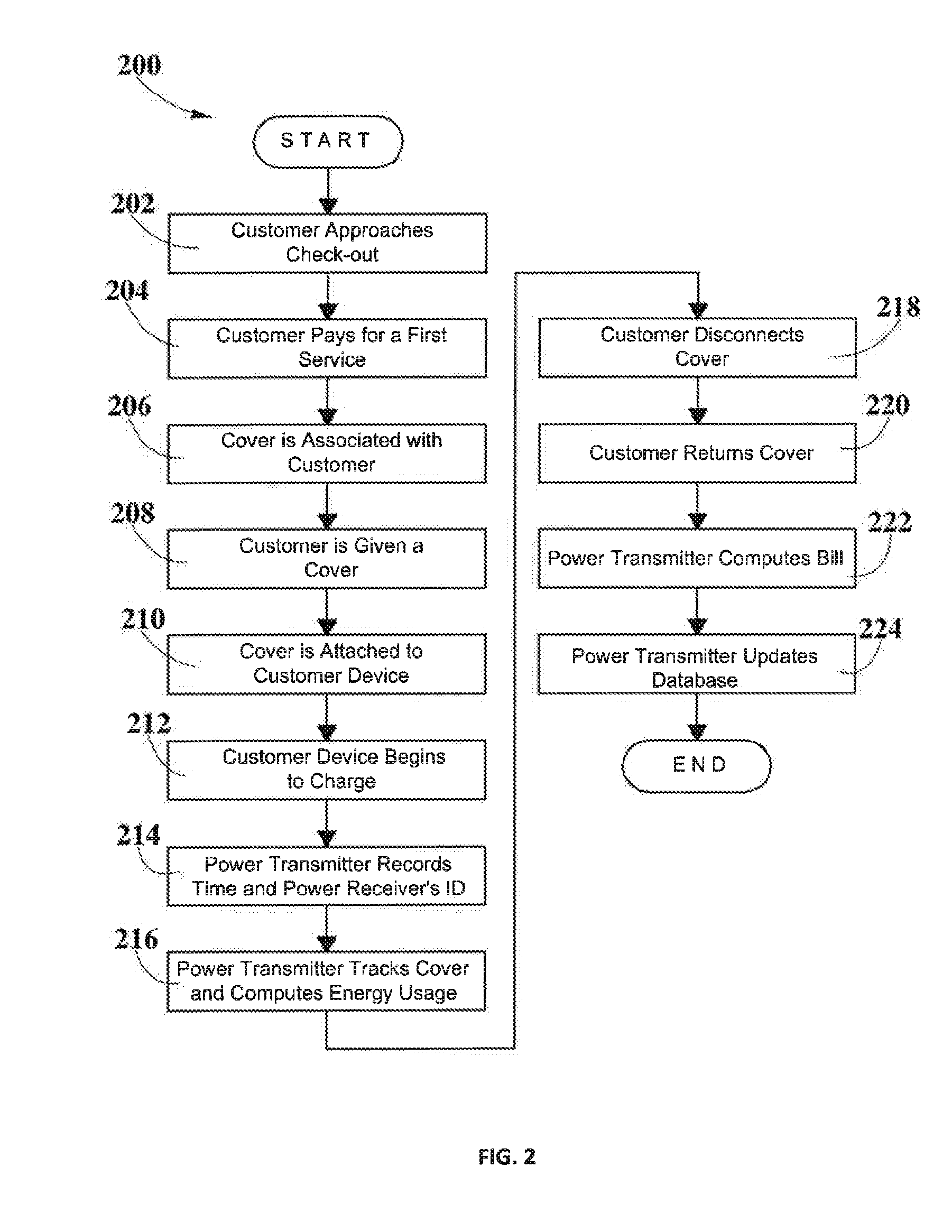
[0053]In example #1 a customer enters a coffee shop and buys a cup of coffee. At checkout, the costumer asks for power to charge a smartphone. The customer's smartphone includes a suitable GUI for interacting with a wireless charging system. A cover with an embedded power receiver is associated with the customer and the customer receives the cover. Then, the smartphone is paired with a power receiver embedded in the smartphone cover. The smartphone starts receiving power and the power transmitter keeps records of the time, amount of power delivered to the smartphone, position of the power receiver and any suitable information needed. After some time, the smartphone reaches a desired level of charge and the customer disconnects the power receiver and returns it to the check-out. The power transmitter computes the bill based on the amount of power delivered to the smartphone and updates the database. The customer's electronic device is charged and the process ends.

[0054]In example #2 ...


PUM


Abstract

Various exemplary embodiments of the present disclosure describe systems and methods for charging electronic devices using wireless power delivery systems. The described systems include one or more wireless power transmitters, one or more wireless power receivers and one or more electronic devices. Electronic devices may be able to communicate with wireless power transmitters and wireless power receivers using suitable communications channels. The disclosed systems are capable of associating a wireless power receiver with a customer to deliver power to a customer's device.

Description

BACKGROUND[0001]1. Field of the Disclosure[0002]The present disclosure relates in general to wireless power transmission, and more specifically to methods for delivering power to customers.[0003]2. Background Information[0004]Electronic devices such as laptop computers, smartphones, portable gaming devices and tablets, amongst others, may require power for performing their intended functions. This may require having to charge electronic equipment at least once a day, or in high-demand electronic devices more than once a day. Such an activity may be tedious and may represent a burden to users. For example, a user may be required to carry chargers in case his electronic equipment is lacking power. In addition, users have to find available power sources to connect to. Additionally, users may be required to plugin to a wall or other power supply to be able to charge his or her electronic device. However, such an activity may in some cases render electronic devices inoperable during char...

Claims


Application Information

Patent Timeline
Patent Type & Authority Applications(United States)
IPC IPC(8): H02J7/02H02J17/00G06Q30/04
CPCH02J7/025H02J17/00G06Q30/04H02J50/20H02J50/80
Inventor BELL, DOUGLASLEABMAN, MICHAEL
Owner ENERGOUS CORPORATION
Why Eureka
Try Eureka