Heater and image heating apparatus including the same

a heating apparatus and image technology, applied in the direction of heater elements, instruments, electrographic processes, etc., can solve the problem of large gap between the electroconductive lines and the possibility of large potential differences therebetween, and achieve the effect of suppressing the increase of the substrate width

Active Publication Date: 2015-11-26
CANON KK
View PDF0 Cites 14 Cited by
  • Summary
  • Abstract
  • Description
  • Claims
  • Application Information

AI Technical Summary

Benefits of technology

[0011]It is an object of the present invention to provide a heater with which the increase of the width of the substrate is suppressed.

Problems solved by technology

Therefore, the gap between the electroconductive lines with the possibility of large potential difference therebetween tends to be large.

Method used


Image

  • Heater and image heating apparatus including the same
  • Heater and image heating apparatus including the same
  • Heater and image heating apparatus including the same

Examples


embodiment 1

Image Forming Apparatus

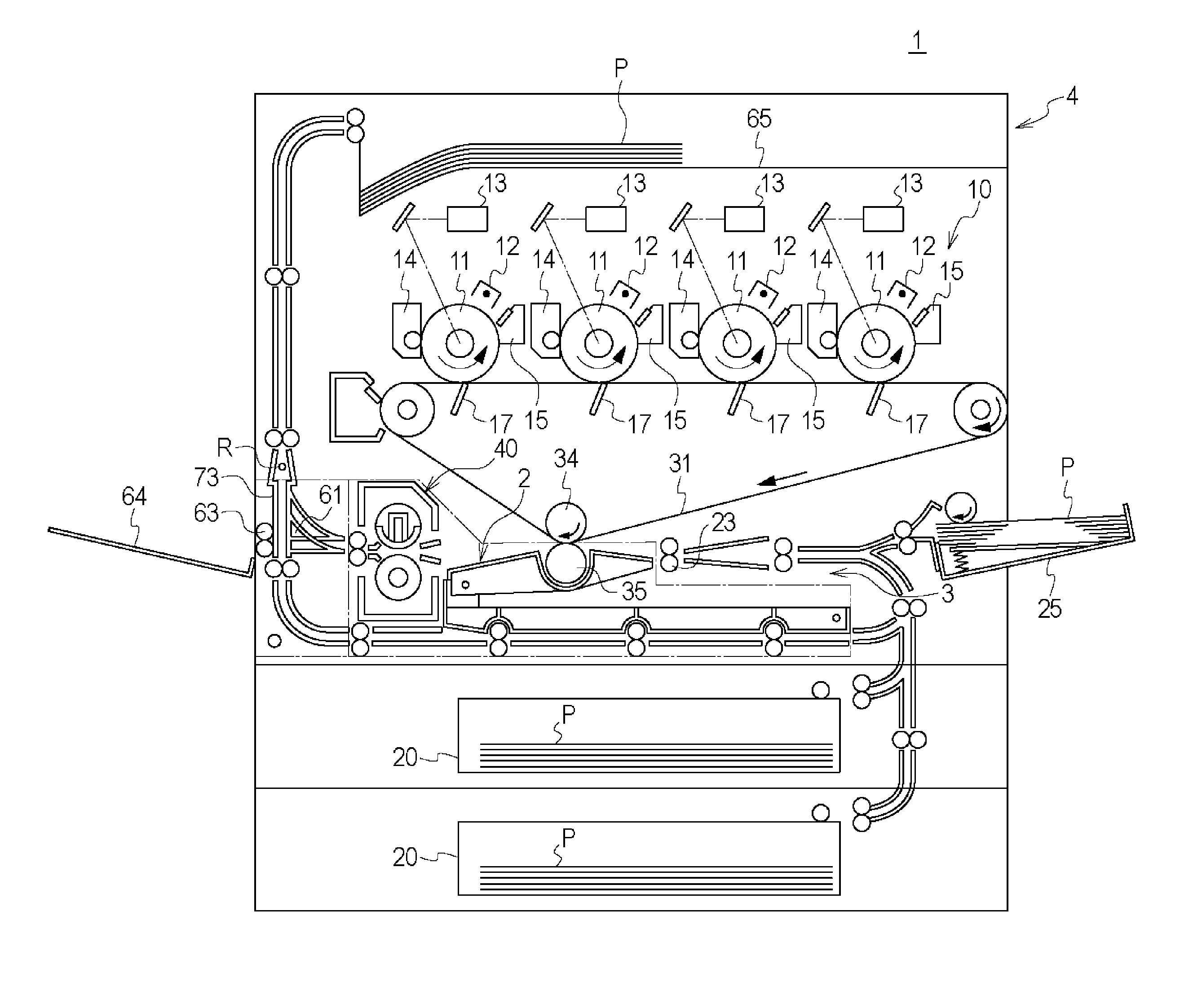
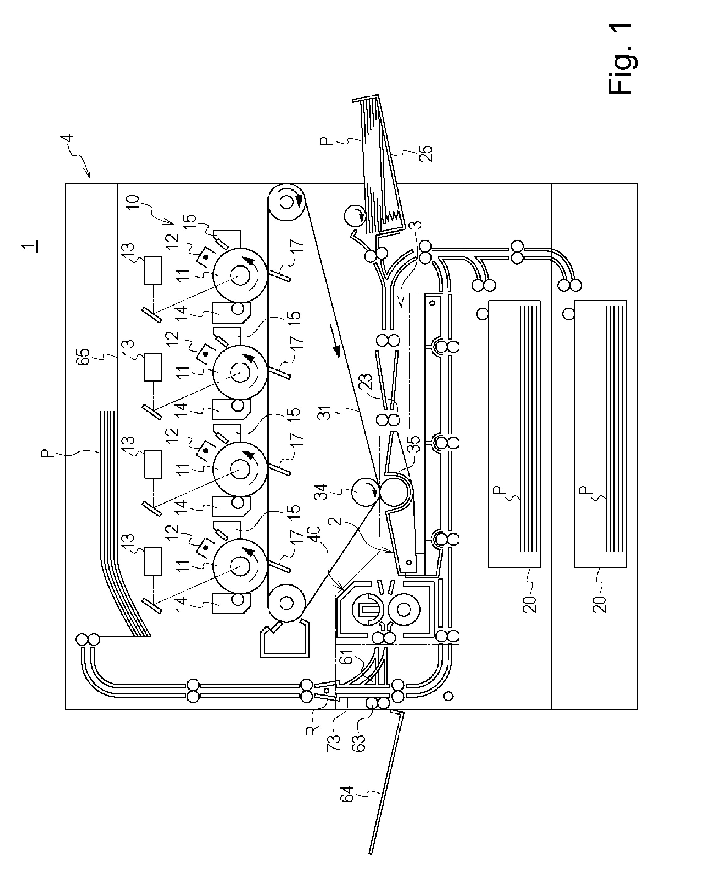
[0034]FIG. 1 is a sectional view of the printer 1 which is the image forming apparatus of this embodiment. The printer 1 comprises an image forming station 10 and a fixing device 40, in which a toner image formed on the photosensitive drum 11 is transferred onto a sheet P, and is fixed on the sheet P, by which an image is formed on the sheet P. Referring to FIG. 1, the structures of the apparatus will be described in detail.

[0035]As shown in FIG. 1, the printer 1 includes image forming stations 10 for forming respective color toner images Y (yellow), M (magenta), C (cyan) and Bk (black). The image forming stations 10 includes respective photosensitive drums 11 (11Y, 11M, 11C, 11Bk) corresponding to Y, M, C, Bk colors are arranged in the order named from the left side. Around each drum 11, similar elements are provided as follows: A charger 12 (12Y, 12M, 12C, 12Bk); Exposure device 13 (13Y, 13M, 13C, 13Bk); Developing device 14 (14Y, 14M, 14C, 14Bk); A primary ...

embodiment 2

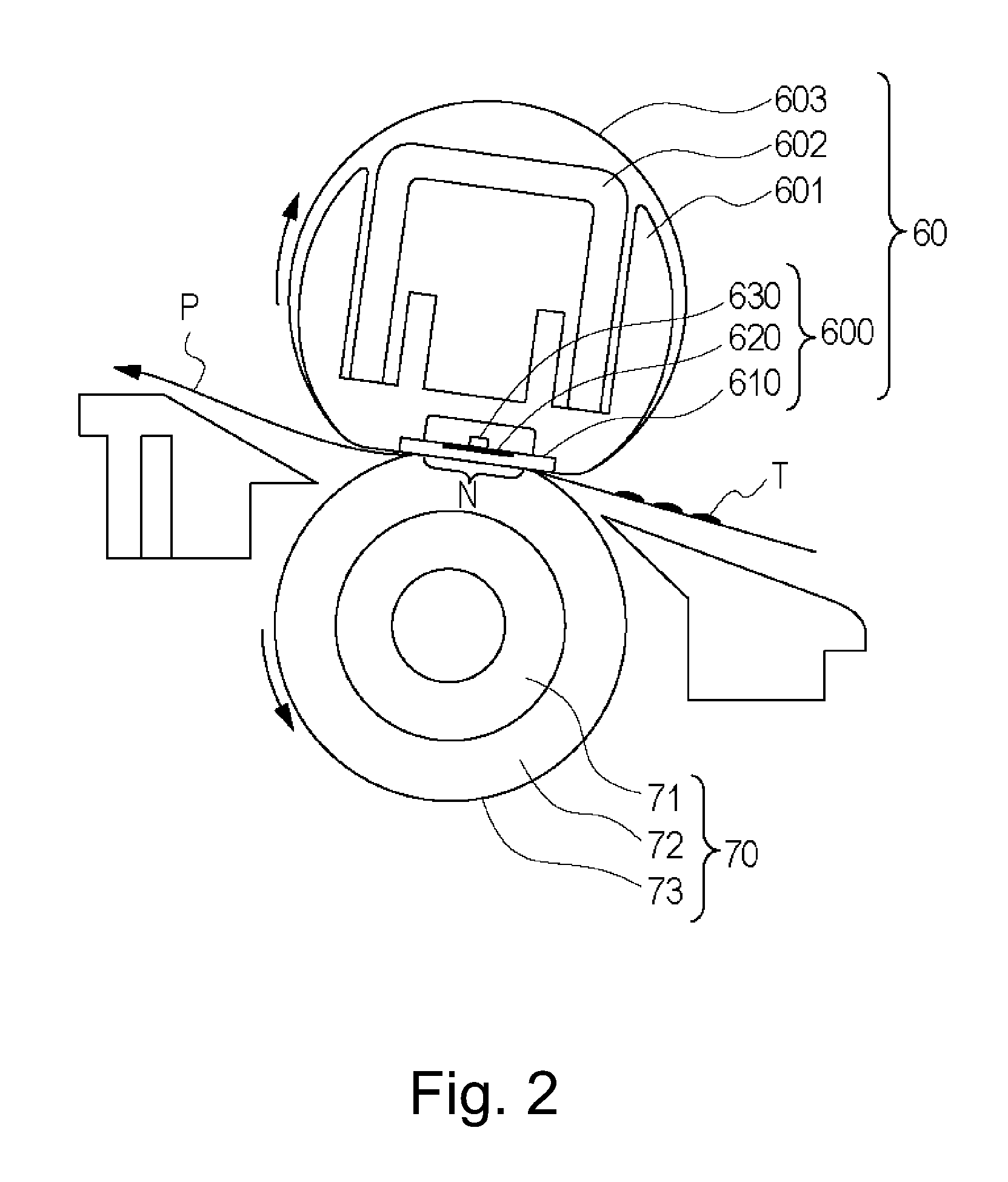
[0110]A heater 600 according to Embodiment 2 of the present invention will be described. FIG. 10 is an illustration of a structure relation of the image heating apparatus of this embodiment. FIG. 11 illustrates the arrangement of the electroconductive lines on the substrate 610.

[0111]In Embodiment 1, the heat generation region of the heat generating element 620 is switched between a heat generation region A and a heat generation region B (Two patterns). In Embodiment 2, the heat generation region of the heat generating element 620 is switched between a heat generation region A, a heat generation region B and a heat generation region C. With this structure of this embodiment, the sheet P can be heated with more suitable heat generation widths for a variety of width sizes of the sheets. The structures of the fixing device 40 of Embodiment 2 are fundamentally the same as those of Embodiment 1 except for the structures relating to the heater 600. In the description of this embodiment, t...

embodiment 3

[0129]A heater according to Embodiment 3 of the present invention will be described. FIG. 12 is an illustration of a structure relation of the image heating apparatus of this embodiment. FIG. 13 illustrates an arrangement of the electroconductive lines on the heater of this embodiment. In Embodiment 1, the heat generating element 620 is supplied with the electric energy from the electrical contacts disposed in the opposite longitudinal end portions of the substrate 610. In Embodiment 3, the heat generating element 620 it is supplied with the electric energy from the electrical contacts provided one longitudinal end portion of the substrate 610. More particularly, the electrical contact 661b and electrical contact 661a of Embodiment 1 are gathered into a common electrical contact 661a. The 651b electrical contact is gathered into the electrical contact 651a. The 651b electrical contact is gathered into the electrical contact 651a. With such a structure, the number of electrical conta...


PUM


Abstract

A heater usable with an image heating apparatus including first and second terminals includes electrodes including first and second electrodes connectable the first and second terminals, respectively, the first electrodes and the second electrodes extend longitudinally; heat generating portions between adjacent electrodes; a first electric line connected with the first electrodes, the first line being extending with a gap between the heat generating portions, a second electric line connected with the second electrode connected with the heat generating portions in a first heat generating region, a third electric line connected with the second electrode connected with the heat generating portions in a second heat generating region, the second electric line being extended adjacent to the second electric line, wherein a gap between the second and third electric lines in the widthwise direction is smaller than the gap between the first and second electrodes in the widthwise direction.

Description

FIELD OF THE INVENTION AND RELATED ART[0001]The present invention relates to a heater for heating an image on a sheet and an image heating apparatus provided with the same. The image heating apparatus is usable with an image forming apparatus such as a copying machine, a printer, a facsimile machine, a multifunction machine having a plurality of functions thereof or the like.[0002]An image forming apparatus is known in which a toner image is formed on the sheet and is fixed on the sheet by heat and pressure in a fixing device (image heating apparatus). As for such a fixing device, a type of fixing device is recently proposed (Japanese Laid-open Patent Application 2012-37613) in which a heat generating element (heater) is contacted to an inner surface of a thin flexible belt to apply heat to the belt. Such a fixing device is advantageous in that the structure has a low thermal capacity, and therefore, the temperature rise to the fixing operation allowable is quick.[0003]Such a fixing...

Claims


Application Information

Patent Timeline
Patent Type & Authority Applications(United States)
IPC IPC(8): H05B3/00H05B3/06G03G15/20H05B3/03
CPCH05B3/0014G03G15/2053H05B3/06H05B3/03G03G15/2039H05B3/0095G03G2215/2035G03G15/2042
Inventor NAKAYAMA, TOSHINORI
Owner CANON KK
Why Eureka
Try Eureka