Air leak detection device and electrically powered suction equipment provided therewith

a technology of air leak detection and suction equipment, which is applied in the direction of suction drainage containers, intravenous devices, other medical devices, etc., can solve the problems of air leakage into the thoracic cavity of patients and difficulty in observing the generation of air bubbles

Active Publication Date: 2015-12-03
SENKO MED INSTR MFG CO LTD
View PDF11 Cites 11 Cited by
  • Summary
  • Abstract
  • Description
  • Claims
  • Application Information

AI Technical Summary

Benefits of technology

[0015]Since, according to this electrically powered suction equipment, the pressure between the water seal chamber and the electrically operated vacuum pump is measured, and the generation of air bubbles is detected on the basis of these pressure fluctuations, accordingly it is possible to detect leakage of air into the thorax of the patient without observation of the air bu...

Problems solved by technology

After thorax surgery or during pneumothorax treatment, air leaks into a thoracic cavity of a patient.
However it is difficult to observe the generation of a...

Method used


Image

  • Air leak detection device and electrically powered suction equipment provided therewith
  • Air leak detection device and electrically powered suction equipment provided therewith
  • Air leak detection device and electrically powered suction equipment provided therewith

Examples


embodiment # 1

Embodiment #1

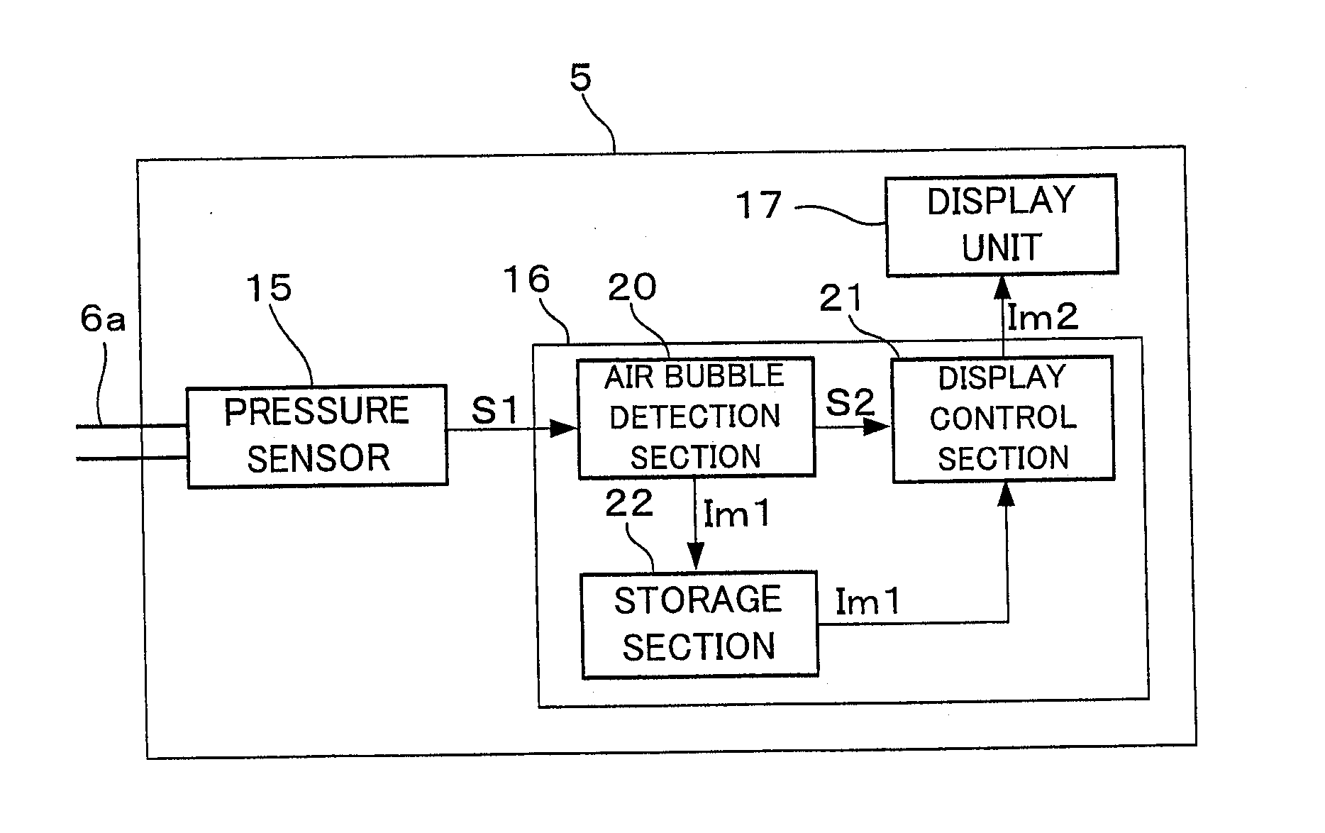
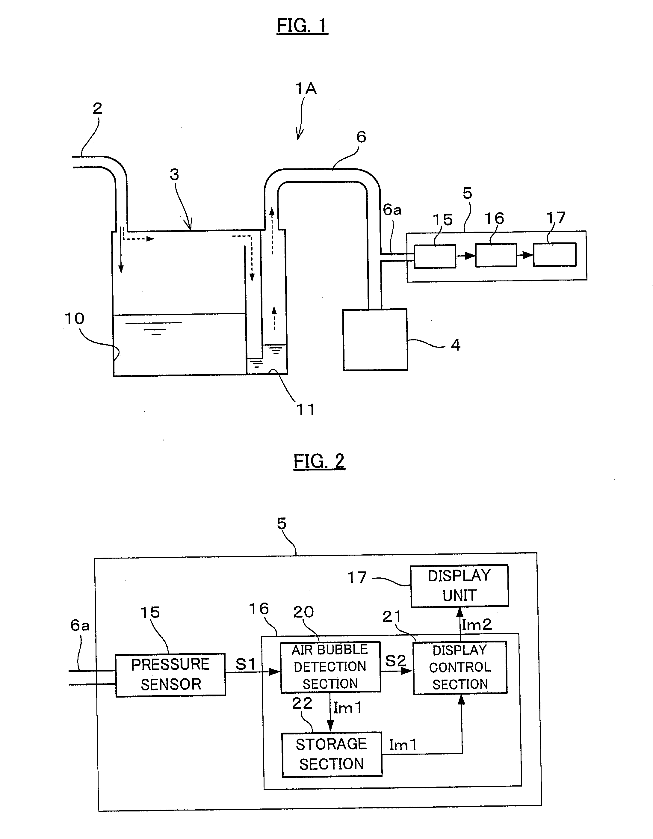
[0024]As shown in FIG. 1, a thoracic cavity drain system 1A is employed for discharging air that has leaked into the thoracic cavity of a patient, or liquid such as blood or the like that has accumulated within the thoracic cavity, to the exterior of the body of the patient. This thoracic cavity drain system 1A comprises a drain tube 2 that is indwelt in the thoracic cavity of a patient who has experienced thoracic surgery or of a patient under pneumothorax treatment, a thoracic cavity drain bag 3 connected to this drain tube 2, a vacuum source 4 connected to the thoracic cavity drain bag 3 via an suction circuit 6, and an air leak detection device 5 connected to the suction circuit 6 and provided between the thoracic cavity drain bag 3 and the vacuum source 4. It should be understood that, in order to prevent aspiration at excessive negative pressure in the suction circuit 6, a pressure regulation chamber that is communicated to the atmosphere and that is filled with l...

embodiment # 2

Embodiment #2

[0033]Next, a second embodiment of the present invention will be explained with reference to FIG. 3. This second embodiment is one in which the present invention is implemented as an electrically powered suction equipment that is equipped with an air leak detection device 5 according to the first embodiment. In the following, the same reference symbols will be appended to structures that are the same as in the first embodiment, and explanation thereof will be omitted.

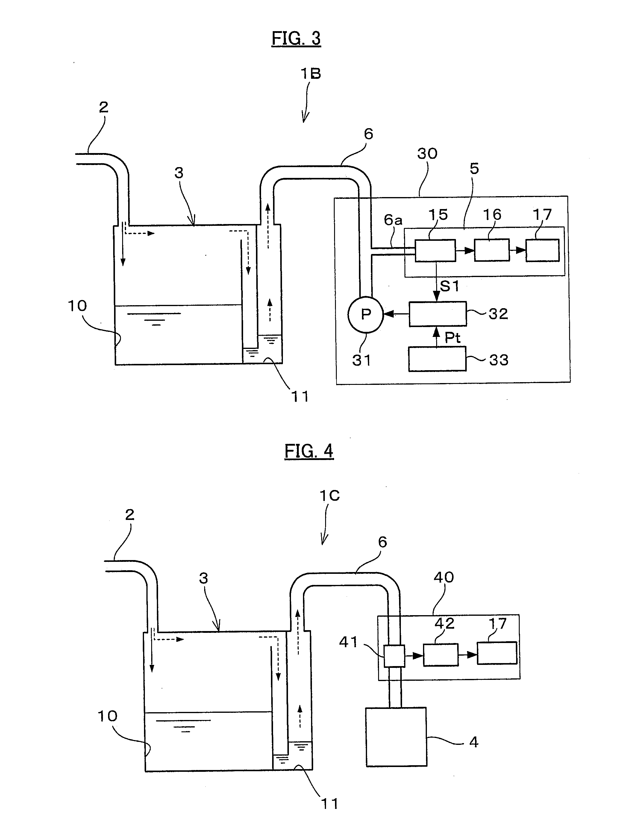
[0034]As shown in FIG. 3, a thoracic cavity drain system 1B comprises a thoracic cavity drain bag 3 that is connected to a drain tube 2, and an electrically powered suction equipment 30 that is connected to the thoracic cavity drain bag 3 via an suction circuit 6. The electrically powered suction equipment 30 comprises an electrically powered vacuum pump 31 that is connected to the suction circuit 6, a pump control section 32 that controls the electrically operated vacuum pump 31, and an aspiration conditio...

embodiment # 3

Embodiment #3

[0036]Next, a third embodiment of the present invention will be explained with reference to FIGS. 4 and 5. This third embodiment is characterized in that the flow rate from the water seal chamber toward the vacuum source is measured, and the generation of air bubbles is detected on the basis of fluctuations of this flow rate. The thoracic cavity drain system 1C shown in FIG. 4 is the same as that of the first embodiment, except that an air leak detection device 40 is provided, instead of the air leak detection device 5 according to the first embodiment. In the following, the same reference symbols will be appended in FIG. 4 to structures that are the same as in the first or the second embodiment, and explanation thereof will be omitted.

[0037]The air leak detection device 40 is provided between the water seal chamber 11 and the vacuum source 4. And a flow rate sensor 41 is provided to the suction circuit 6, and serves as a flow rate measurement device that measures the f...


PUM


Abstract

An air leak detection device is applied to a thoracic cavity drainage system which, by using negative pressure generated by a vacuum source, aspirates gas in the thoracic cavity of a patient via a water seal chamber in which liquid is received. The pressure between the vacuum source and the water seal chamber is measured by a pressure sensor, and the occurrence of air bubbles created in the water seal chamber is detected on the basis of fluctuations of this pressure.

Description

CROSS-REFERENCE TO RELATED PATENT APPLICATIONS[0001]This application is a U.S. National Phase Application under 35 U.S.C. §371 of International Patent Application No. PCT / JP2014 / 050842, filed Jan. 17, 2014, and claims the benefit of Japanese Patent Application No. 2013-007155, filed Jan. 18, 2013, all of which are incorporated by reference in their entirety herein. The International Application was published in Japanese on Jul. 24, 2014 as International Publication No. WO / 2014 / 112598 under PCT Article 21 (2).FIELD OF THE INVENTION[0002]The present invention relates to an air leak detection device that is capable of detecting air leak in which air is leaking into the thoracic cavity of a patient, and to an electrically powered suction equipment that is provided with such a device.BACKGROUND OF THE INVENTION[0003]After thorax surgery or during pneumothorax treatment, air leaks into a thoracic cavity of a patient. Such leaking of air into the thoracic cavity of the patient is generally...

Claims


Application Information

Patent Timeline
IPC IPC(8): A61M1/00
CPCA61M1/0025A61M2205/15A61M1/0031A61M1/0013A61M2205/3331A61M2205/3334A61M2210/101A61M1/61A61M1/73A61M1/74
Inventor YOKOI, HIROSHIICHIKAWA, NORIHISAKATSUTA, SOUICHIKIHARA, MASAHIRO
Owner SENKO MED INSTR MFG CO LTD
Why Eureka
Try Eureka