Polishing apparatus

a technology of polishing apparatus and end point detection, which is applied in the direction of lapping machines, instruments, manufacturing tools, etc., can solve the problems of short circuits, increased resistance value, and insufficient isolation of circuits, so as to improve the accuracy of polishing end point detection

Active Publication Date: 2015-12-03
EBARA CORP
View PDF19 Cites 10 Cited by
  • Summary
  • Abstract
  • Description
  • Claims
  • Application Information

AI Technical Summary

Benefits of technology

[0025]According to the present invention, accuracy of polishing end point detection can be improved.

Problems solved by technology

In the polishing apparatus, if the polishing target is insufficiently polished, there arises a concern that circuits are not insulated from each other, which causes short circuit with each other.
Moreover, in the case of excessive polishing, the cross-sectional area of the wiring decreases to cause such problems that the resistance value increases, or the wiring itself is completely removed and thereby the circuit itself is not formed.
The conventional technology, however, does not consider improvement of accuracy of the polishing end point detection.
In the seal portion, sliding friction due to the rotating body and the housing arises, and the sliding friction results in driving load of the driving unit which drives the rotating body.
When some cause results in a change in driving load due to the sliding friction of the seal portion, there is a concern that this change is directly reflected to the motor current and causes false detection of the polishing end point.

Method used


Image

  • Polishing apparatus
  • Polishing apparatus
  • Polishing apparatus

Examples


Embodiment Construction

[0033]Hereafter, a polishing apparatus according to an embodiment of the present invention is described based on the drawings. First, a basic configuration of the polishing apparatus is described, and after that, detection of the polishing end point of a polishing target is described.

Basic Configuration

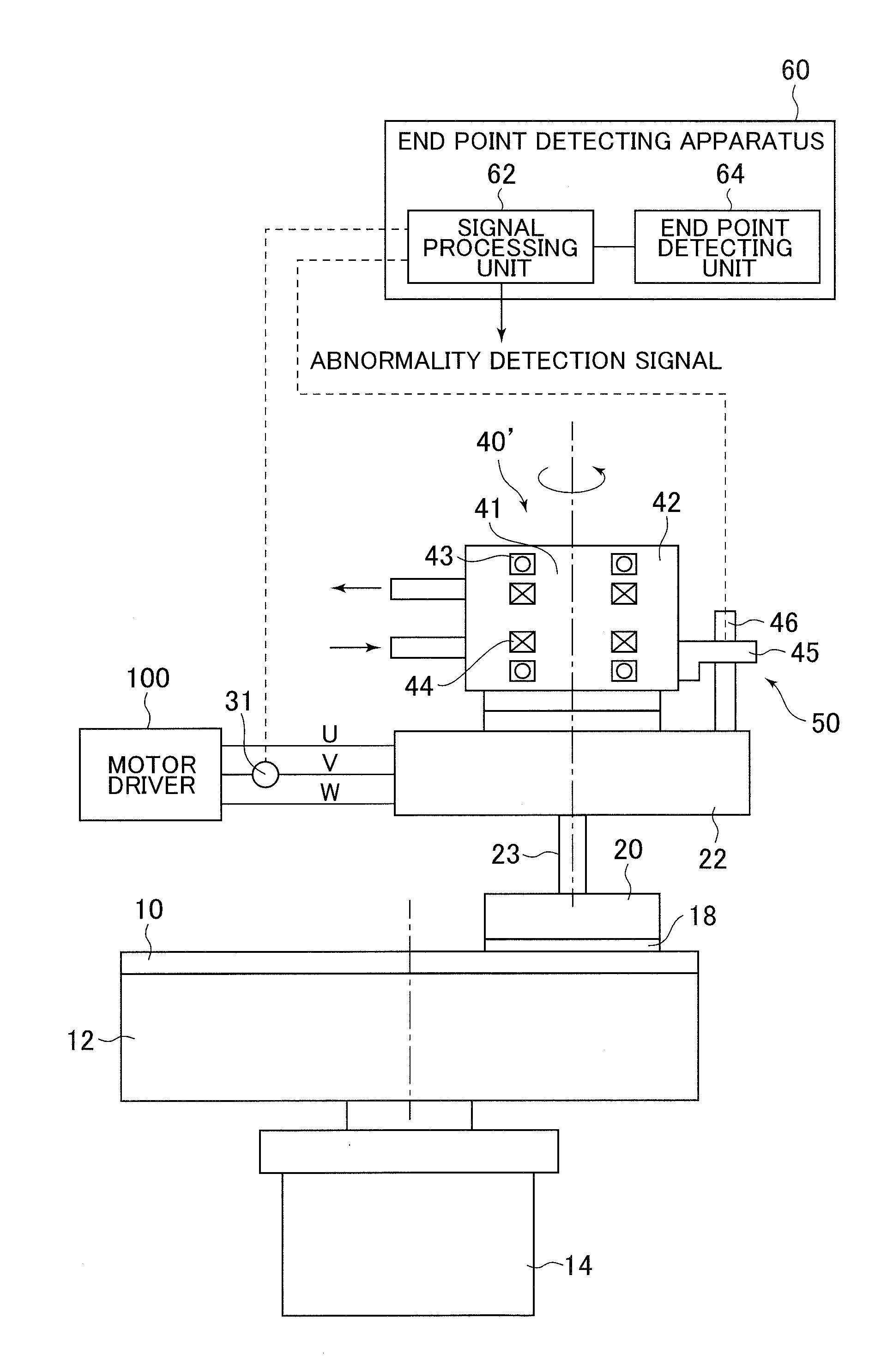
[0034]FIG. 1 is a diagram illustrating a basic configuration of a polishing apparatus according to the present embodiment. The polishing apparatus includes a polishing table 12 on the upper surface of which a polishing pad 10 can be attached, a first electric motor (first driving unit) 14 which rotationally drives the polishing table 12, a position detecting sensor 16 which detects the rotational position of the first electric motor, a top ring (substrate holding unit) 20 which can hold a semiconductor wafer 18, and a second electric motor (second driving unit) 22 which rotationally drives the top ring 20.

[0035]The top ring 20 can be brought close to and separated from the polishing t...


PUM


Abstract

A polishing apparatus includes: a polishing table 12 for holding a polishing pad; a first electric motor 14 that rotationally drives the polishing table 12; a first rotary joint 40 that has a rotating body 41 that is rotationally driven by the first electric motor 14, a housing 42 provided around the rotating body 41, and a seal portion 44 that seals between the rotating body 41 and the housing 42; a second current sensor 31 that detects a current which is correlated with driving load of the first electric motor 14; a friction detecting unit 50 that detects sliding friction in the seal portion 44 of the first rotary joint 40; and an end point detecting apparatus 60 that detects a polishing end point of the polishing target on the basis of the current and the sliding friction.

Description

CROSS REFERENCE TO RELATED APPLICATION[0001]This application claims priority to Japanese Patent Application No. 2014-114672 filed Jun. 3, 2014, the entire contents of which are hereby incorporated by reference.[0002]The present invention relates to a polishing apparatus.BACKGROUND OF THE INVENTION[0003]In recent years, following the high integration of semiconductor devices, wirings of circuits have been miniaturized, and the distance between the wirings has also been reduced. Therefore, it is necessary to flatten the surface of a semiconductor wafer, which is a polishing target, and as one of the flattening methods, a semiconductor wafer is polished by using a polishing apparatus.[0004]Conventionally, the polishing apparatus includes a polishing table for holding a polishing pad for polishing the polishing target, and a top ring holding the polishing target to be pressed onto the polishing pad. The polishing table and the top ring are rotationally driven by driving units (for examp...

Claims


Application Information

Patent Timeline
Patent Type & Authority Applications(United States)
IPC IPC(8): B24B37/013B24B49/10B24B49/16B24B37/10
CPCB24B37/013B24B49/16B24B49/10B24B37/107G01N19/02
Inventor SHINOZAKI, HIROYUKI
Owner EBARA CORP
Why Eureka
Try Eureka