Elevator car position detection device

a technology for detecting devices and cars, applied in the direction of elevators, instruments, transportation and packaging, etc., can solve the problems of generating step, elongation of main ropes, and landing errors, and achieve the effects of reducing eddy current magnetic field, low cost, and increasing position detection precision

Inactive Publication Date: 2015-12-03
MITSUBISHI ELECTRIC CORP
View PDF5 Cites 24 Cited by
  • Summary
  • Abstract
  • Description
  • Claims
  • Application Information

AI Technical Summary

Benefits of technology

[0015]In the elevator car position detection device according to the one embodiment of the present invention, the identification member includes the plurality of conductors relatively different in the plate thickness with respect to the skin depth of the eddy current generated by the magnetic field generator on the identification member, and when the sensor detects the identification member, in which of ranges of the conductors of the identification member the car is positioned is identified based on the information on the amplitude and the phase of the eddy current magnetic field acquired from the output of the magnetic field detector. Therefore, it is possible to detect the position of the car for a plurality of zones more precisely at low cost. Moreover, the shape of at least a part of the boundary between the conductors adjacent to each other is set as the straight line or the curve tilted with respect to the direction orthogonal to the ascending and descending direction of the car. Thus, even when the position of the sensor is shifted by a lateral swing of the car with respect to the identification member, a reduction in the eddy current magnetic field generated on a part adjacent to the boundary may be suppressed, and the shift in the detection position may thus be suppressed, resulting in an increase in position detection precision.

Problems solved by technology

However, actually, the main ropes slip on the drive sheave, and the main ropes are elongated.
In other words, when the car is intended to land on a certain floor, and the motor is controlled based on the output pulse count of the encoder so that a step between a floor surface of the car and a floor surface of a landing is zero, a landing error, namely, a step may be generated.
The optical type out of those types can highly precisely detect the identification plate, but has such a disadvantage as being sensitive to dust, water drops, and ambient light.

Method used


Image

  • Elevator car position detection device
  • Elevator car position detection device
  • Elevator car position detection device

Examples


first embodiment

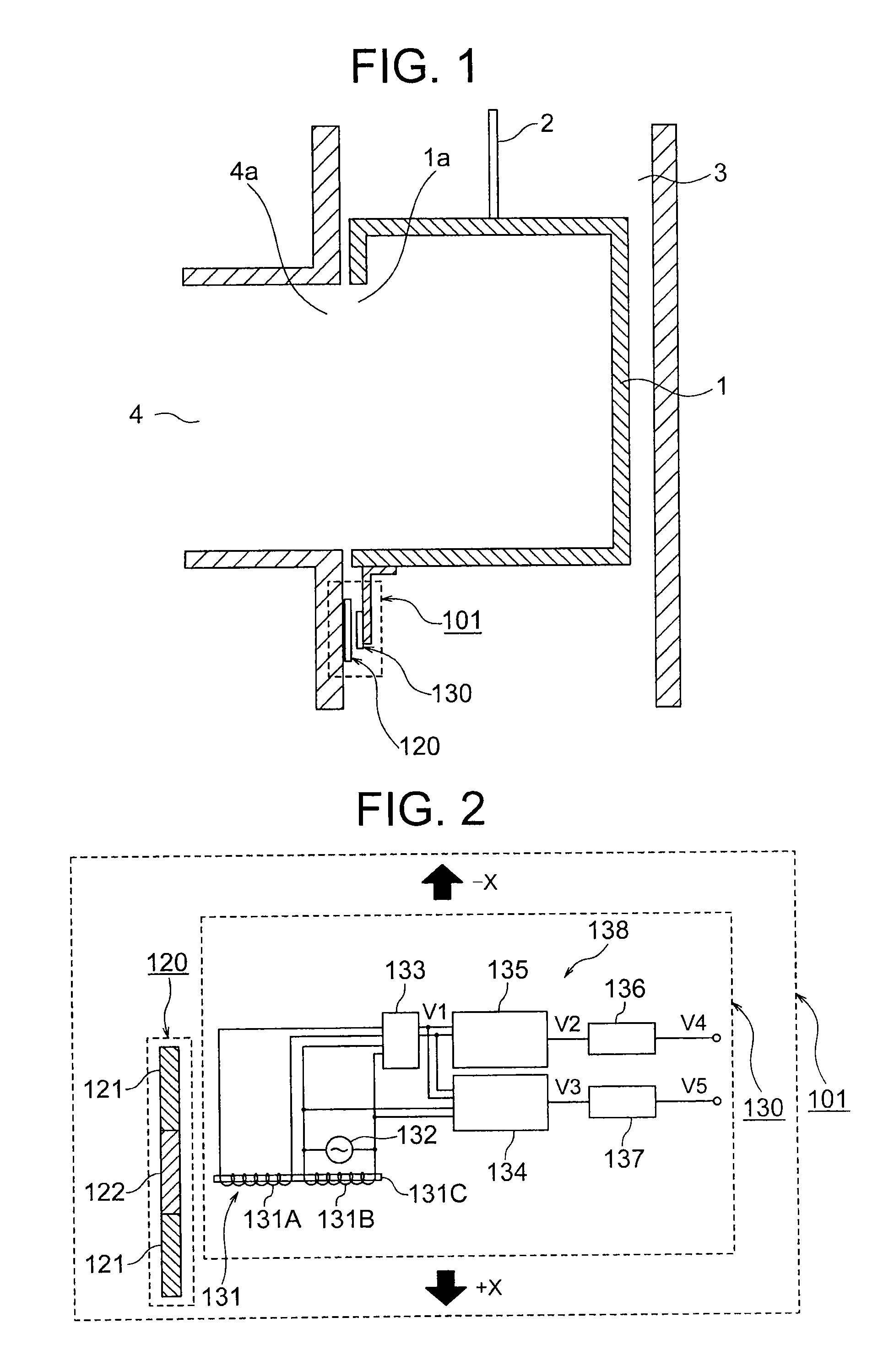
[0052]FIG. 1 is a schematic configuration diagram illustrating a main part of an elevator of a first embodiment of the present invention. In FIG. 1, a car 1 and a counterweight (not shown) are suspended by suspension means 2 in a hoistway 3, and are raised and lowered by a hoisting machine (not shown). As the suspension means 2, a plurality of ropes or belts are used.

[0053]The hoisting machine includes a drive sheave, a motor for rotating the drive sheave, and a brake for braking the rotation of the drive sheave. The suspension means 2 is wound around the drive sheave. An encoder for generating an incremental pulse in response to a rotation of a rotational shaft of the motor is connected to the hoisting machine.

[0054]A car doorway 1a is formed in a front surface of the car 1. The car doorway 1a is opened and closed by a car door device (not shown). Landing doorways 4a are respectively formed in landings 4 on a plurality of floors. Each landing doorway 4a is opened and closed by a la...

second embodiment

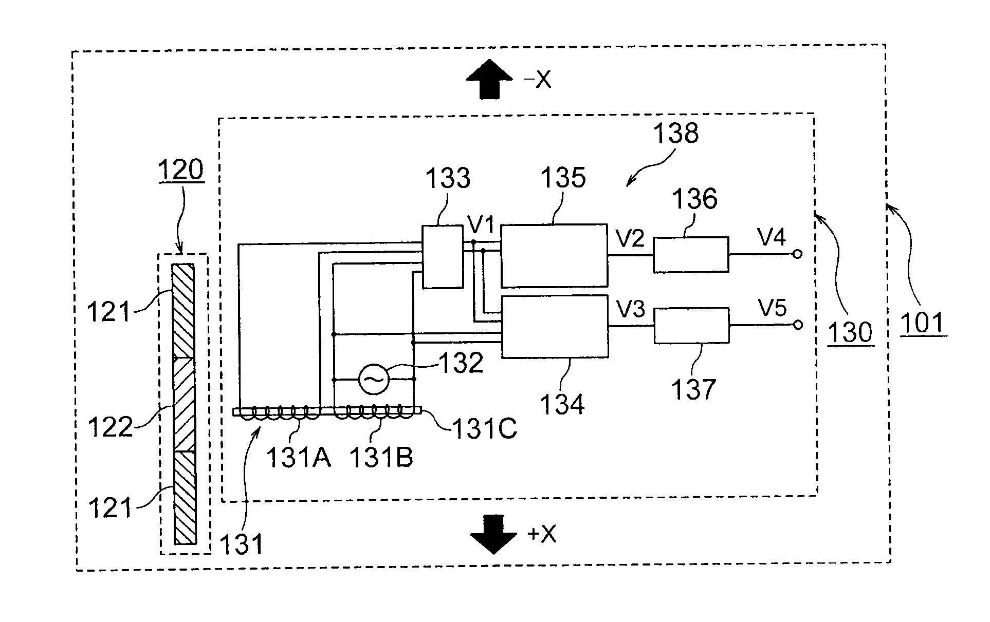
[0134]FIG. 29 is a configuration diagram illustrating an elevator car position detection device of a second embodiment of the present invention. In a car position detection device 102 of the second embodiment, the detection coil 131A and the excitation coil 131B are arranged on both sides of the identification plate 120 in the direction orthogonal to the ascending and descending direction. This configuration is the same as the configuration of FIG. 25. Note that, a sensor 130-4 of FIG. 29 is different from the sensor 130-2 of FIG. 25 in such a point that the AC magnetic field component removal circuit 133 is omitted. Then, in the configuration of FIG. 29, the detection coil 131A outputs a voltage acquired by combining the AC magnetic field and the eddy current magnetic field.

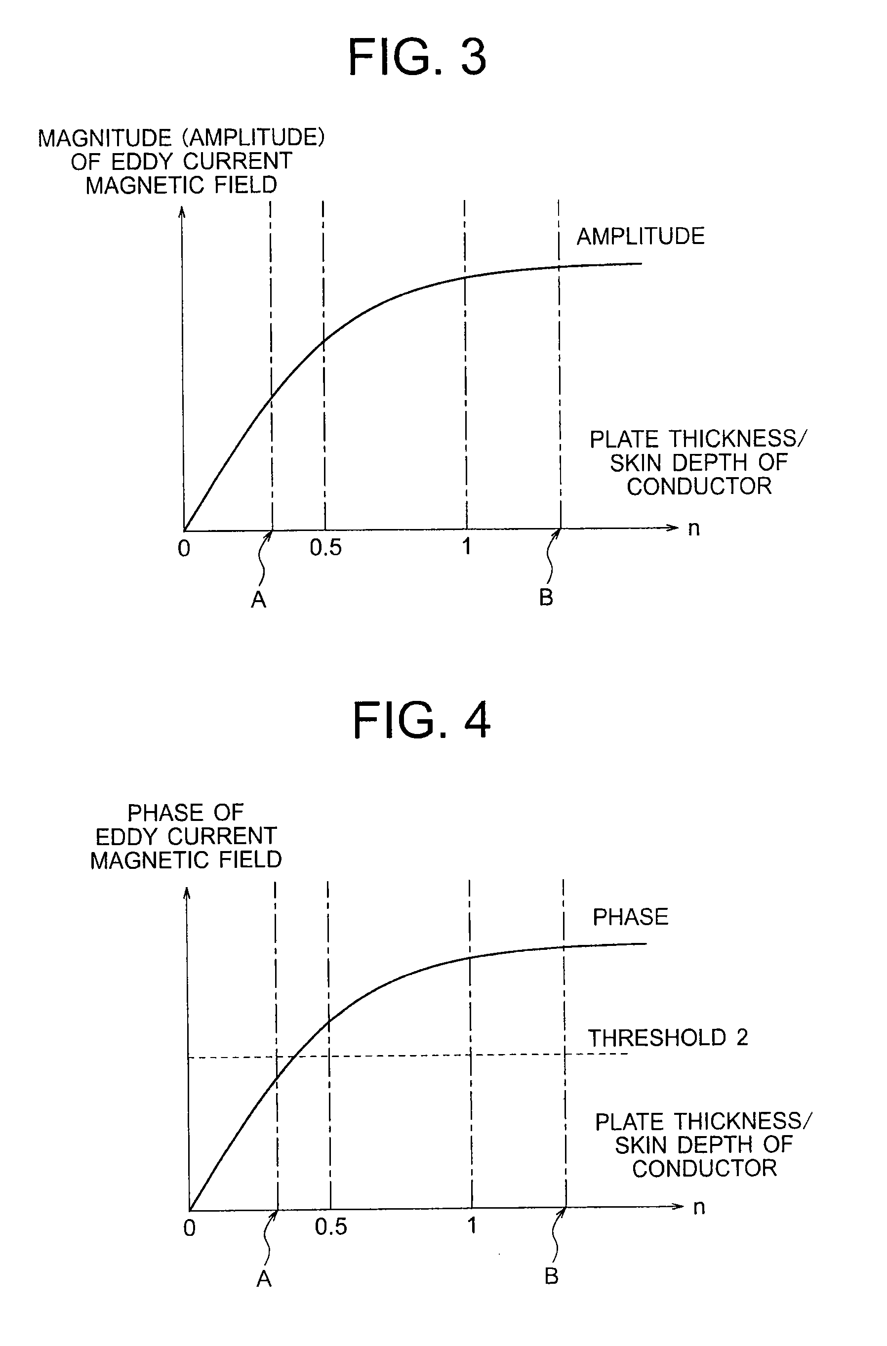
[0135]FIG. 30 is a graph showing a relationship between a magnitude (amplitude) of the detected magnetic field (the composite magnetic field of the AC magnetic field and the eddy current magnetic field) and a ra...

third embodiment

[0150]FIG. 35 is an explanatory diagram illustrating a relationship between the positions of the detection coil 131A and the excitation coil 131B with respect to the identification plate 120 of an elevator car position detection device of a third embodiment of the present invention, the output V2 of the amplitude value detection circuit 135, the output V3 of the phase difference detection circuit 134, the output V4 of the amplitude value comparator 136, and the output V5 of the phase difference comparator 137.

[0151]The configuration of the car position detection device of the third embodiment is the same as the configuration of the car position detection device 101 of the above-mentioned first embodiment. Note that, the car position detection device of the third embodiment is different from that of the first embodiment in such a point that two thresholds (a threshold 3 and a threshold 4) are set to the phase difference comparator 137. A detailed description is now given of this diff...


PUM


Abstract

In an elevator car position detection device, a magnetic field generator generates an eddy current magnetic field on an identification member, and a magnetic field detector detects the eddy current magnetic field generated on the identification member. The identification member includes a plurality of conductors which are continuously arranged along an ascending and descending direction of a car, and are relatively different in a plate thickness with respect to a skin depth of an eddy current generated by the magnetic field generator on the identification member. A shape of at least a part of a boundary between the adjacent conductors is a straight line or a curve tilted with respect to a direction orthogonal to the ascending and descending direction of the car.

Description

TECHNICAL FIELD[0001]The present invention relates to an elevator car position detection device for detecting a position of a car through detection of an identification member with a sensor.BACKGROUND ART[0002]In a related-art elevator, a car and a counterweight are suspended in a hoistway by a plurality of main ropes. The main ropes are wound around a drive sheave of a hoisting machine. Then, the car and the counterweight are raised and lowered by a motor of the hoisting machine rotating the drive sheave.[0003]An encoder for generating an incremental pulse in response to a rotation of a rotational shaft of the motor is connected to the motor. The position of the car can be detected by counting the incremental pulse from the encoder.[0004]However, actually, the main ropes slip on the drive sheave, and the main ropes are elongated. Therefore, in the method of counting the output pulse of the encoder, a difference may be generated between a detected car position and an actual car posi...

Claims


Application Information

Patent Timeline
Patent Type & Authority Applications(United States)
IPC IPC(8): B66B1/34G01D5/20
CPCG01D5/20B66B1/3492
Inventor INOUE, JINKURATA, EMIKOWATANABE, YOSHIMASASHIRATSUKI, AKIHIDENISHIZAWA, HIROSHINAKAJIMA, HAJIMEISHIKAWA, MASAHIRO
Owner MITSUBISHI ELECTRIC CORP
Why Eureka
Try Eureka