
Modular Air Cooled Condenser Apparatus and Method

a condenser and air-cooled technology, applied in the direction of carburetor air, lighting and heating equipment, separation processes, etc., can solve the problems of increasing the back pressure of the turbine, wet or dry cooling towers, and difficult to efficiently and effectively direct steam

Inactive Publication Date: 2015-12-03
SPG DRY COOLING USA LLC
View PDF10 Cites 13 Cited by
  • Summary
  • Abstract
  • Description
  • Claims
  • Application Information

AI Technical Summary

Benefits of technology

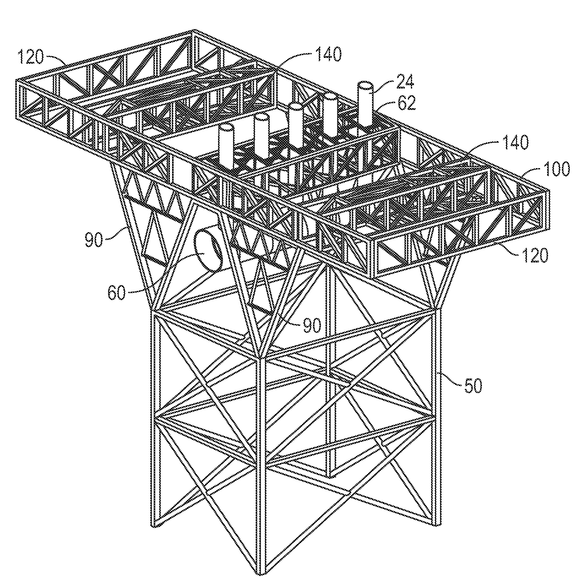
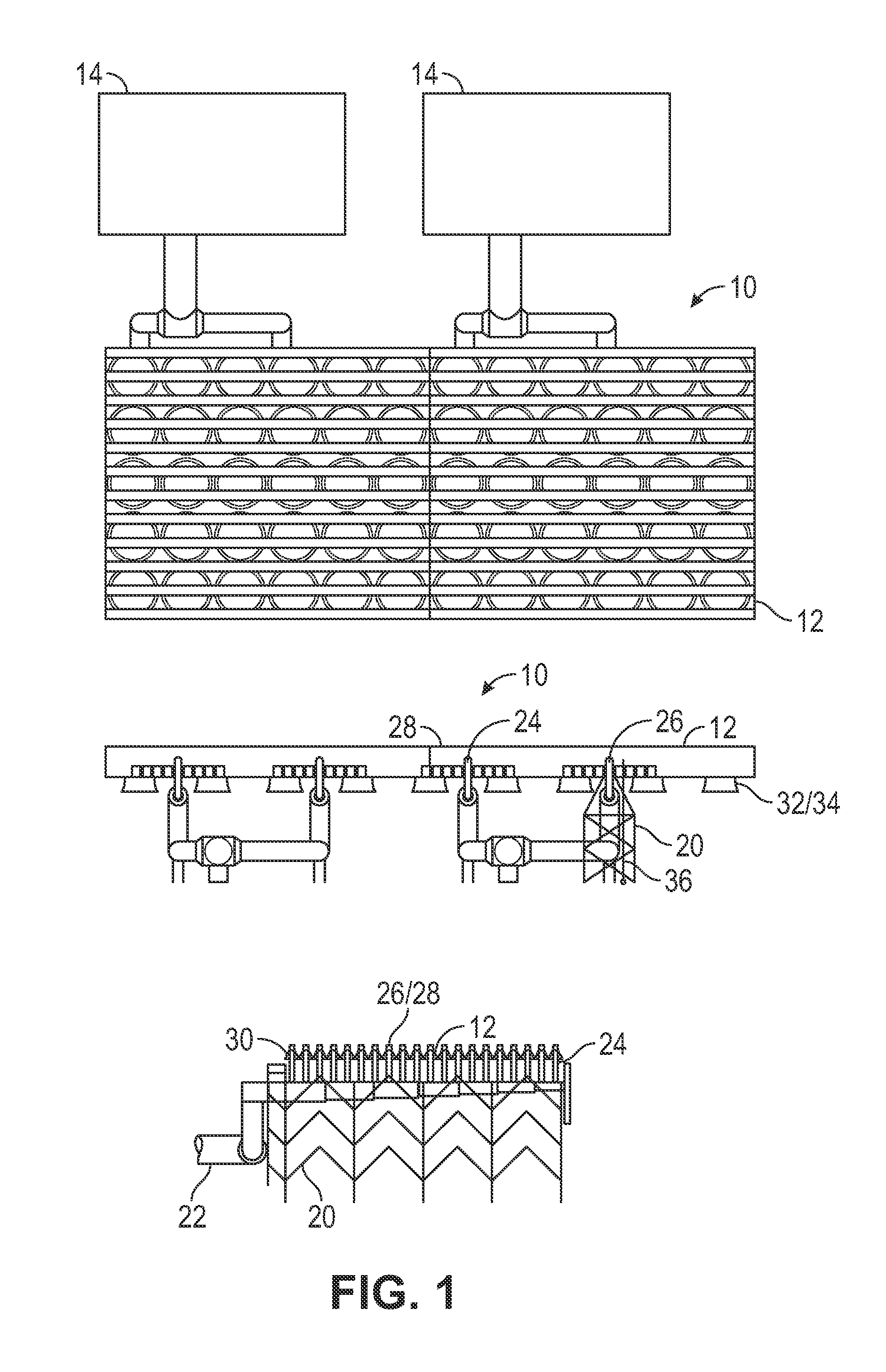
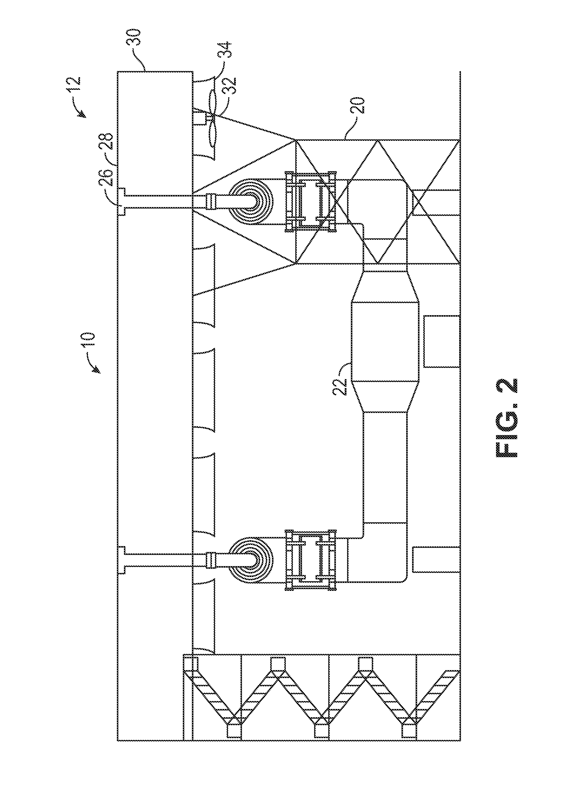
The present invention provides a modular mechanical draft cooling tower for condensing steam. The invention includes a plenum and a support frame for housing an air current generator. The invention also includes first and second condenser bundles with associated tubes, steam manifold, and condensate header. The first and second bundles are placed in a container and transported to the assembly location. A heat exchange delta is assembled by combining the first and second bundles, and the bundle is positioned on a modular tower frame. The technical effects of the invention include improved cooling efficiency, compact design, and flexibility in assembly location.

Problems solved by technology

Cooling towers may be wet or dry.
To accomplish the required direct dry cooling the condenser typically requires a large surface area to dissipate the thermal energy in the gas or steam and oftentimes may present several challenges to the design engineer.
It sometimes can be difficult to efficiently and effectively direct the steam to all the inner surface areas of the condenser because of non-uniformity in the delivery of the steam due to system ducting pressure losses and velocity distribution.
Another challenge or drawback is, while it is desirable to provide a large surface area, steam side pressure drop may be generated thus increasing turbine back pressure and consequently reducing efficiency of the power plant.
Another drawback to the current air cooled condenser towers is that they are typically very labor intensive in their assembly at the job site.
The assembly of such towers oftentimes requires a dedicated labor force, investing a large amount of hours.
Accordingly, such assembly is labor intensive requiring a large amount of time and therefore can be costly.

Method used


Image

  • Modular Air Cooled Condenser Apparatus and Method
  • Modular Air Cooled Condenser Apparatus and Method
  • Modular Air Cooled Condenser Apparatus and Method

Examples


Embodiment Construction

[0039]In the following detailed description, reference is made to the accompanying drawings, which form a part hereof and show by way of illustration specific embodiments in which the invention may be practiced. These embodiments are described in sufficient detail to enable those skilled in the art to practice them, and it is to be understood that other embodiments may be utilized, and that structural, logical, processing, and electrical changes may be made. It should be appreciated that any list of materials or arrangements of elements is for example purposes only and is by no means intended to be exhaustive. The progression of processing steps described is an example; however, the sequence of steps is not limited to that set forth herein and may be changed as is known in the art, with the exception of steps necessarily occurring in a certain order.

[0040]Embodiments described herein provide a heat exchange system, a support structure for an air cooled condenser (“ACC”), and a metho...


PUM

PropertyMeasurementUnit
heightaaaaaaaaaa
lengthaaaaaaaaaa
lengthaaaaaaaaaa

Abstract

The present invention relates to a mechanical draft cooling tower that employs air cooled condenser modules. The aforementioned cooling tower operates by mechanical draft and achieves the exchange of heat between two fluids such as atmospheric air, ordinarily, and another fluid which is usually steam. The aforementioned cooling tower utilizes a modular air cooled condenser concept wherein the air cooled condensers utilize heat exchange deltas that use tube bundles that are manufactured and assembled prior to being shipped to the tower site.

Description

CROSS REFERENCE TO RELATED APPLICATIONS[0001]This application claims priority to U.S. Provisional Application Ser. No. 61 / 828,076, filed on May 28, 2013, titled “MODULAR AIR COOLED CONDENSER APPARATUS AND METHOD,” the disclosure of which is incorporated herein by reference in its entirety.FIELD OF THE INVENTION[0002]The present invention relates to a mechanical draft cooling tower that utilizes air cooled condenser modules. The aforementioned cooling tower operates by mechanical draft and achieves the exchange of heat between two fluids such as atmospheric air, ordinarily, and another fluid which is usually steam or some sort of industrial process fluid. The aforementioned cooling tower operates by mechanical draft which utilizes an air current generator such as a fan or the like.BACKGROUND OF THE INVENTION[0003]Cooling towers are heat exchangers of a type widely used to emanate low grade heat to the atmosphere and are typically utilized in electricity generation, air conditioning i...

Claims


Application Information

Patent Timeline
Patent Type & Authority Applications(United States)
IPC IPC(8): E04H5/12F28C1/00F28F25/00
CPCE04H5/12F28F25/00Y10T29/49636Y10T29/49352F28C1/00E04H5/10F28F9/002F28F9/02F28B1/06F28F2009/029F01K5/02
Inventor QUICKELBERGHE, THOMAS VANBADIN, FRANCISRECHEM, FRANCOIS VANDELEPLANQUE, CHRISTOPHEVOUCHE, MICHEL
Owner SPG DRY COOLING USA LLC
Learn More