Method to optimize chiller plant operation

Inactive Publication Date: 2004-04-13
CHILLER PLANT OPTIMIZATION LLC
View PDF22 Cites 49 Cited by
  • Summary
  • Abstract
  • Description
  • Claims
  • Application Information

AI Technical Summary

Problems solved by technology

During periods of operation, when the chiller is operating at part load, the cooling tower fan, and the cooling fluid pump will be operating at full or a high and unnecessary power setting, thus wasting a substantial amount of energy.
Since the chiller typically operates at part load for most of the time, the amount of wasted energy over time can be quite large.
Since the chiller manufacturer normally does not provide for this type of access, it can only be implemented with the special help from the manufacturer.
A large number of peripheral devices are required a

Method used


Image

  • Method to optimize chiller plant operation
  • Method to optimize chiller plant operation
  • Method to optimize chiller plant operation

Examples


Embodiment Construction

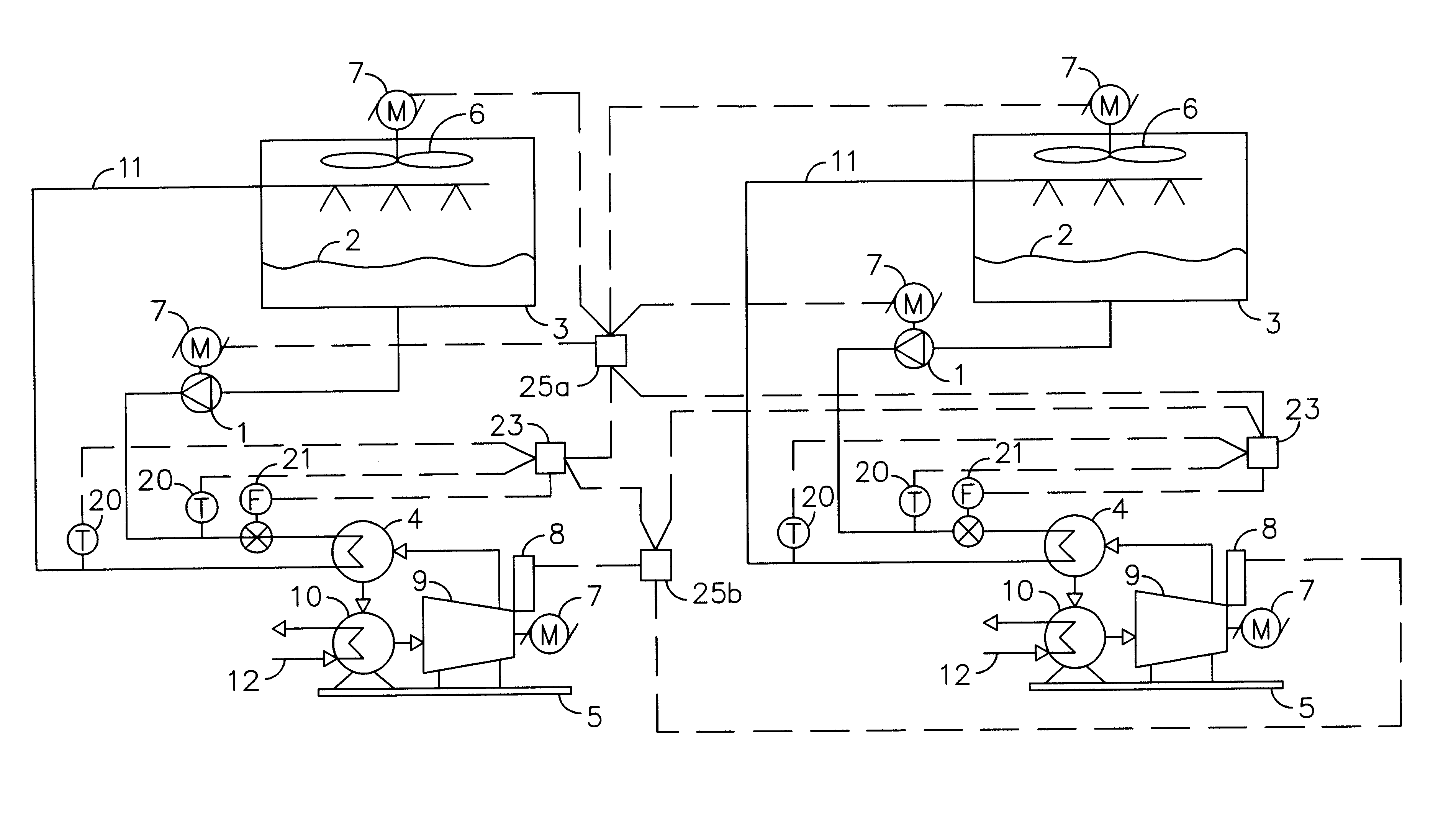
The preferred embodiment of the, present invention is illustrated in FIG. 3. A chiller plant with a plurality of chillers, cooling fluid pumps and cooling towers with fans and a control system that manages the overall operation of the chiller plant to achieve the lowest energy usage and highest energy savings.

A matched pair of temperature sensors (20) are installed in the cooling fluid piping circuit (11) such that the entering cooling fluid temperature and the leaving cooling fluid temperature at the refrigerant condenser (4) are accurately measured. A flow meter (21) is installed in the cooling fluid piping so that it measures the flow rate thru the refrigerant condenser.

A BTU meter (23) receives the temperature signals from each temperature sensor (20) and the flow rate signal from the flow meter (21). An instrument receiver calculates the temperature difference, and if wanted BTU rate. The temperature difference signal, a BTU rate signal, fluid flow rate signal, and entering and...


PUM


Abstract

A chiller plant which produces chilled water for airconditioning, or an industrial process and which is comprised of chillers, cooling fluid pumps, and cooling towers with electrical motor drives uses a substantial amount of energy. A method that coordinates the operation of the cooling tower, cooling fluid pumps, and refrigeration machines so that the chiller plant operates at a higher overall efficiency thus reducing the power usage has been developed and is presented herein. The flow rate of the cooling fluid pumps are controlled to maintain a precise temperature difference across the refrigerant condenser. The cooling tower fans are controlled by comparing the cooling fluid temperature and the cooling fluid flow rate to selected design parameters. The heat rejection rate is measured for each chiller in the chiller plant and operating set points are established for each operating chiller to provide the optimum operation for best energy efficiency.

Description

FEDERALLY SPONSORED RESEARCHNot ApplicableSEQUENCE LISTING OR PROGRAMNot ApplicableBACKGROUND--FIELD OF INVENTIONThis invention relates to a chiller plant, and specifically methods of operation that will reduce the power usage and improve the plants efficiency.BACKGROUND--DISCUSSION OF PRIOR ARTA chiller plant as shown in FIG. 1, includes a chiller (5), a cooling fluid pump (1), a cooling tower (3), and a cooling fluid piping circuit (11) which interconnects these pieces of equipment. The chiller plant produces a chilled fluid that is distributed in a chilled fluid piping circuit (12).The chiller plant may also include a plurality of chillers, pumps, and cooling towers. For instance multiple chillers can be operated in parallel, with a single cooling fluid piping circuit connecting all chillers to the same cooling tower. Another system shown in FIG. 2 has a separate fluid cooling circuit, and separate cooling tower for each individual chiller in the chiller plant.The chiller (5) is ...

Claims


Application Information

Patent Timeline
IPC IPC(8): F25B49/02F28B9/00F28B9/06
CPCF25B49/027F28B9/06F25B2339/047F25B2400/06F25B2700/21161
Inventor HENRY, WILLIAM R.
Owner CHILLER PLANT OPTIMIZATION LLC
Why Eureka
Try Eureka