Capacity control valve

Active Publication Date: 2015-12-03
EAGLE INDS
View PDF4 Cites 36 Cited by
  • Summary
  • Abstract
  • Description
  • Claims
  • Application Information

AI Technical Summary

Benefits of technology

[0044]The present invention exhibits the following superior effects.
[0045](1) According to the first aspect in which the center post which is a constituent member of the solenoid is provided movably in the axial direction in such a manner that one end face thereof is opposed to the second valve portion, and the center post is driven to the direction away from the second valve portion and controlled so that the distance between the second valve portion is increased when discharging the liquid refrigerant, the center post is moved to the direction away from the second valve portion when discharging the liquid refrigerant, so that the passage area of the second valve chamber is dramatically increased compared to the case where the center post is fixed, and the amount of the refrigerant discharged into the suction chamber via the suction-side passages out of the liquid refrigerant or the like accumulating in the control chamber can be dramatically increased.
[0046](2) According to the second aspect in which the end face opposed to the second valve portion of the center post functions as the valve seat face of the second valve portion, the area of the passage for discharging the liquid refrigerant in the second valve chamber can be adjusted using an existing member without providing a special member.
[0047](3) According to the thi

Problems solved by technology

By the way, if the swash plate type variable capacity compressor is stopped and caused to be started after being left for a long time, the liquid refrigerant (the cooled and liquefied refrigerant gas

Method used


Image

  • Capacity control valve
  • Capacity control valve
  • Capacity control valve

Examples


Example

First Embodiment

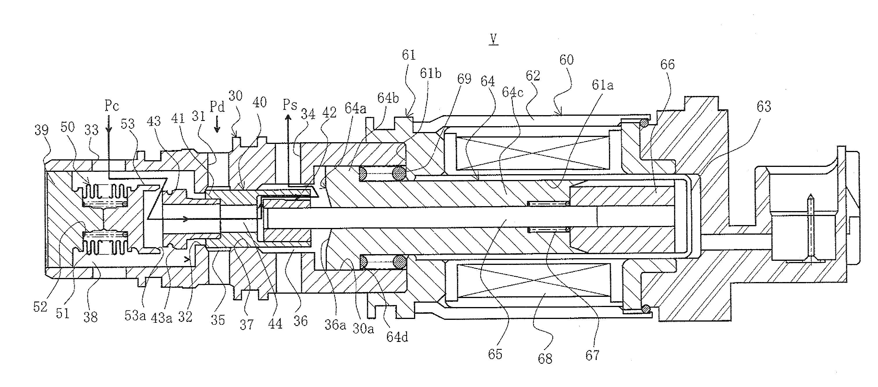
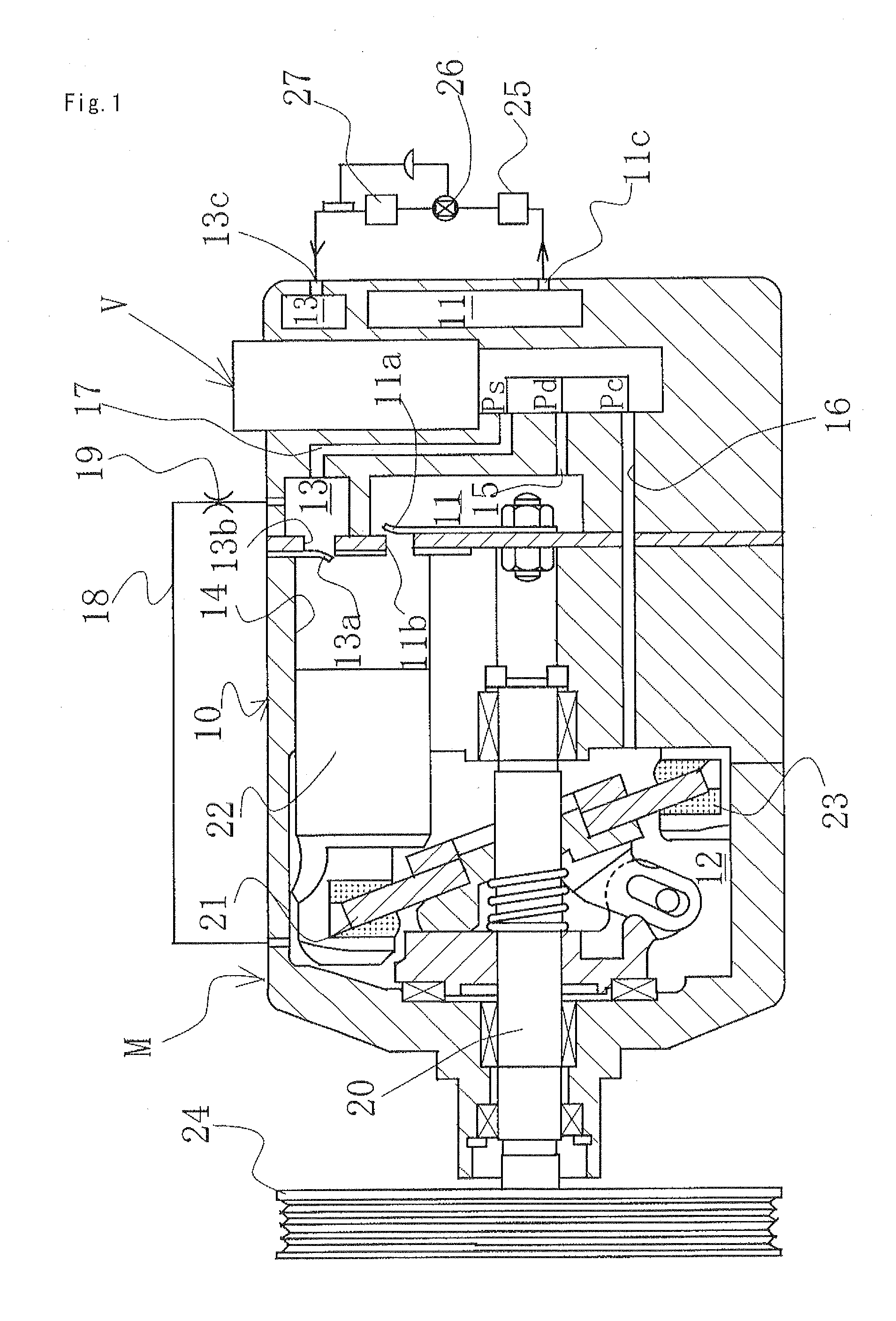
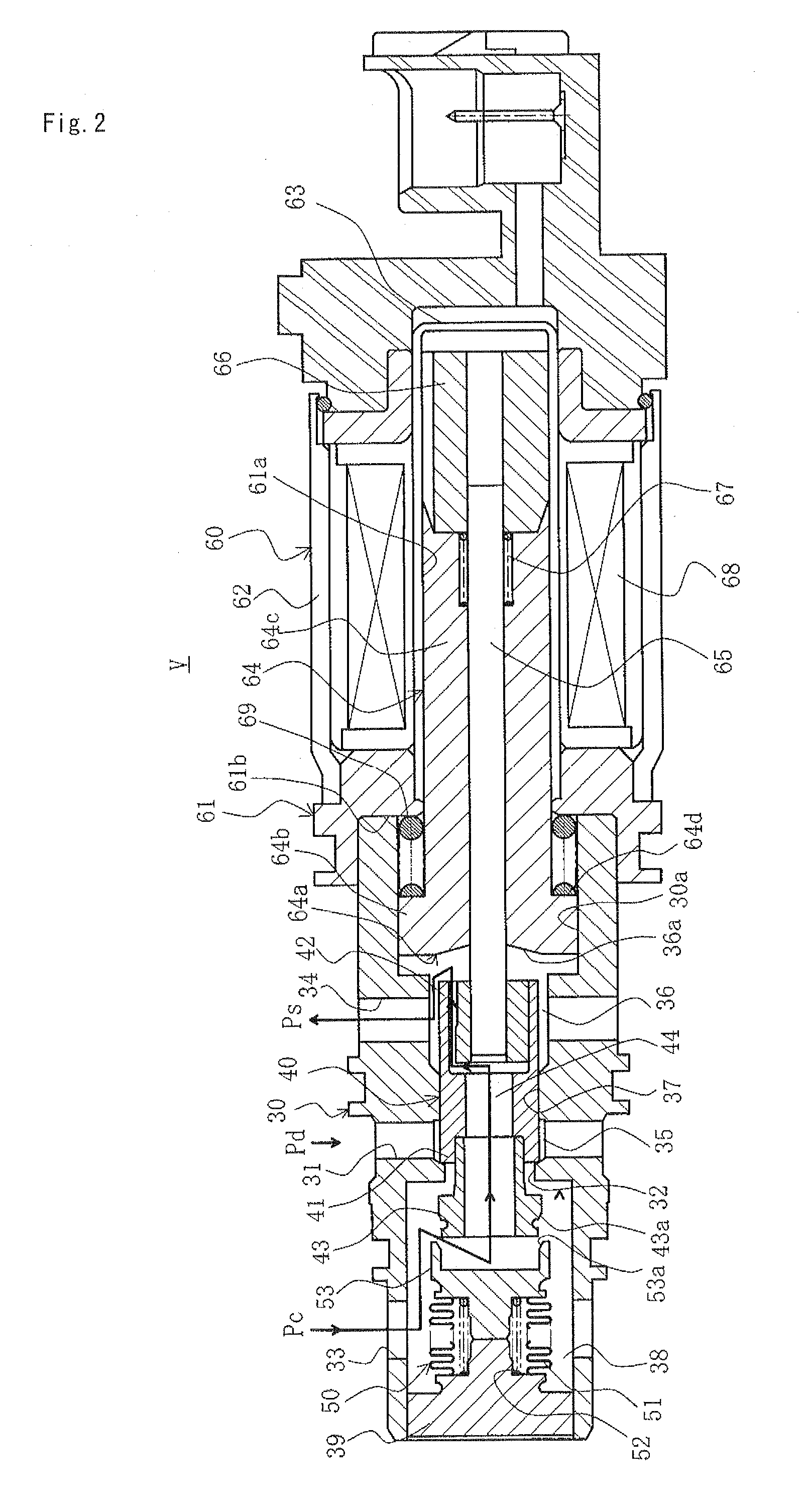
[0071]With reference to FIGS. 1 to 4, a capacity control valve according to a first embodiment of the present invention will be described.

[0072][Swash Plate Type Variable Capacity Compressor with a Capacity Control Valve]

[0073]As shown in FIG. 1, a swash plate type variable capacity compressor M includes a discharge chamber 11, a control chamber (also referred to as a crank chamber) 12, a suction chamber 13, a plurality of cylinders 14, a port 11b opened and closed by a discharge valve 11a for providing communication between the cylinders 14 and the discharge chamber 11, a port 13b opened and closed by a suction valve 13a for providing communication between the cylinders 14 and the suction chamber 13, a discharge port 11c and a suction port 13c connected to an external cooling circuit, communication passages 15, 16 as discharge-side passages for providing communication between the discharge chamber 11 and the control chamber 12, communication passages 16, 17 as sucti...

Example

Second Embodiment

[0111]With reference to FIGS. 5 to 8, a capacity control valve according to a second embodiment of the present invention will be described.

[0112]It should be noted that the same reference signs are given to the same members as the first embodiment and redundant description thereof will be omitted.

[0113]The capacity control valve of the second embodiment shown in FIGS. 5 to 8 is characterized in that a dedicated bypass passage 55 for discharging the liquid refrigerant is provided and the area of the passage for discharging the liquid refrigerant is further increased by opening the bypass passage 55 by means of the operation of the center post 64 only when discharging the liquid refrigerant.

[0114]FIG. 5 shows the capacity control valve according to the second embodiment of the present invention in a first state of discharging the liquid refrigerant.

[0115]In FIG. 5, the bypass passage 55 for providing direct communication between the third valve chamber 38 and the seco...


PUM


Abstract

A control valve for discharging a liquid refrigerant in a control chamber at the time of start-up of a variable capacity compressor has a movable a center post for increasing the area of a passage for discharging the liquid refrigerant when discharging the liquid refrigerant.

Description

TECHNICAL FIELD[0001]The present invention relates to a capacity control valve for variably controlling a capacity or pressure of a working fluid, and particularly relates to a capacity control valve for controlling a discharge rate of a variable capacity compressor or the like used in an air conditioning system of an automobile or the like according to a pressure load.BACKGROUND ART[0002]A swash plate type variable capacity compressor used in an air-conditioning system of an automobile or the like includes a rotating shaft rotatably driven by a rotational force of an engine, a swash plate coupled to the rotating shaft so that the angle of inclination can be varied, a piston for compression coupled to the swash plate, and the like, and varies a stroke of the piston by varying the angle of inclination of the swash plate and controls the discharge rate of a refrigerant gas.[0003]The angle of inclination of the swash plate can be continuously varied by adjusting the state of balance of...

Claims


Application Information

Patent Timeline
IPC IPC(8): F16K31/06F04B27/18F16K11/04
CPCF16K31/0624F16K11/04Y10T137/86485F04B2027/1813F04B27/1804F04B2027/1827F04B2027/1831F04B2027/1845F04B2027/1854
Inventor HIGASHIDOZONO, HIDEKISHIRAFUJI, KEIGOKANZAKI, TOSHINORI
Owner EAGLE INDS
Why Eureka
Try Eureka