Low cost burner

a burner and low-cost technology, applied in the field of low-cost burners, can solve the problems of difficult conception and implementation, and difficulty in achieving

Inactive Publication Date: 2015-12-03
MABE SA DE CV
View PDF8 Cites 32 Cited by
  • Summary
  • Abstract
  • Description
  • Claims
  • Application Information

AI Technical Summary

Benefits of technology

[0013]Yet another aspect of the present invention may be to provide the burner with at least one air ring on the lower p

Problems solved by technology

Present invention lies in the field of gas burners, particularly Bunsen burners used in household appliance equipment, such as stoves, kitchens or cooking surfaces; if there is a large variety of these burners both in the marketplace as well as in the state of the art, these are quite difficult to conceive and put into practice, given that they require extensive laborator

Method used


Image

  • Low cost burner
  • Low cost burner
  • Low cost burner

Examples


Embodiment Construction

Definitions

[0027]The use of the term “approximately” provides an additional determined range. The term is defined in the following manner: the additional range set by the term is approximately ±10%. By way of example, but not in a limitative way, if the term reads “approximately 8 cm”, the exact range lies within 7.2 to 8.8 millimeters.

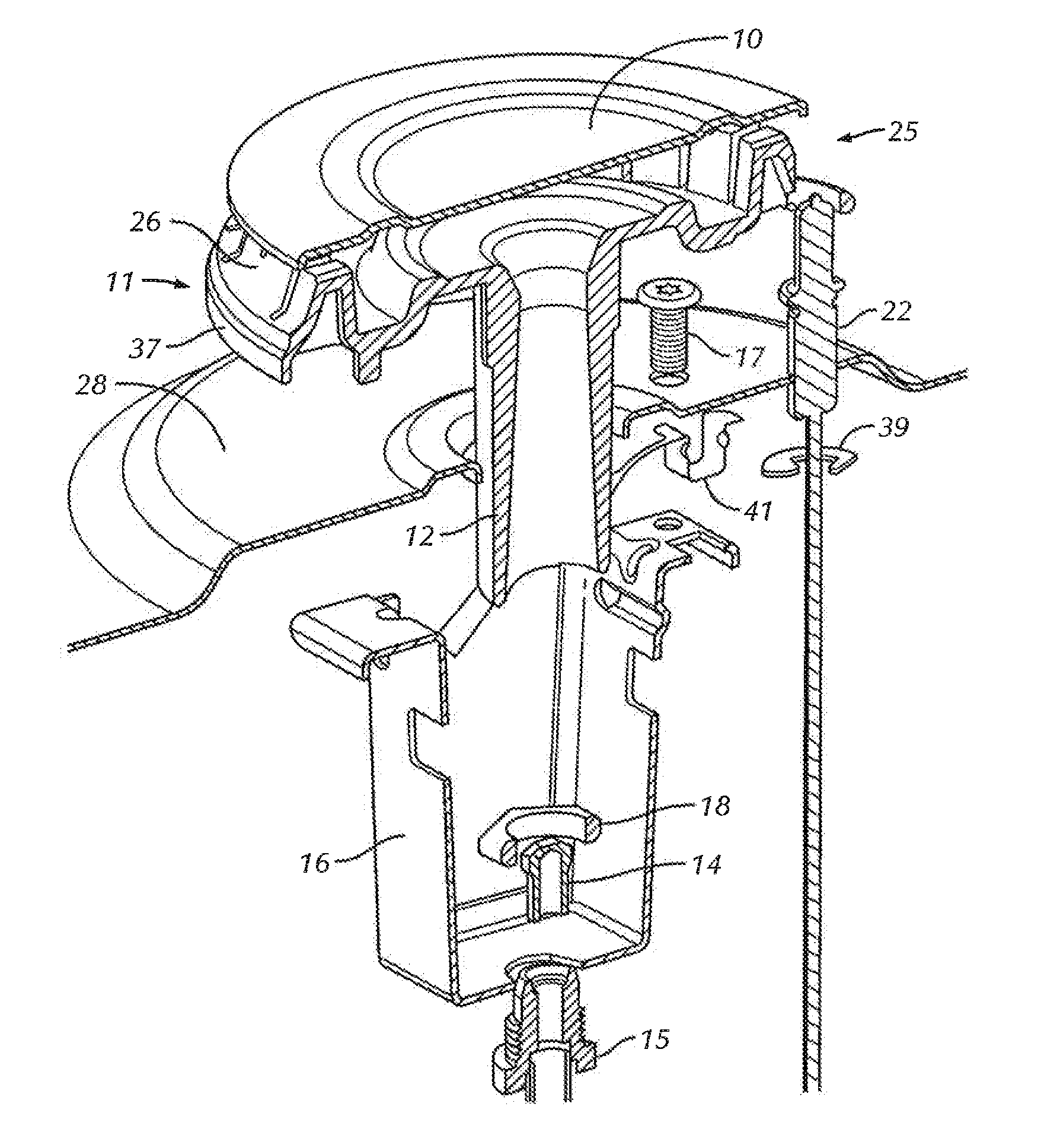
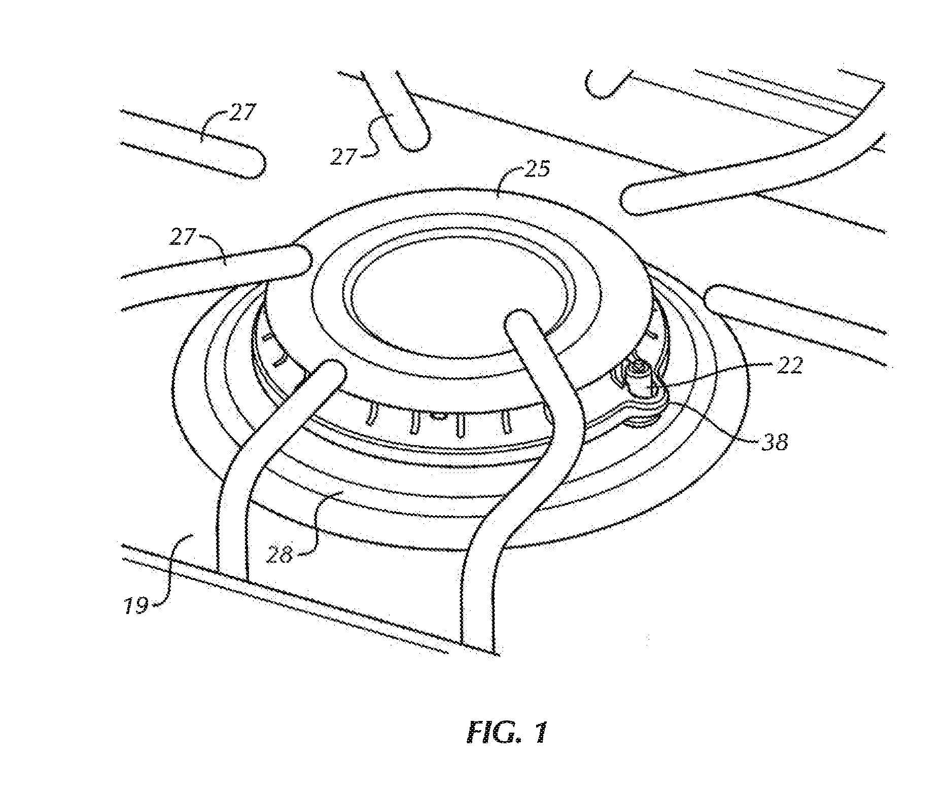
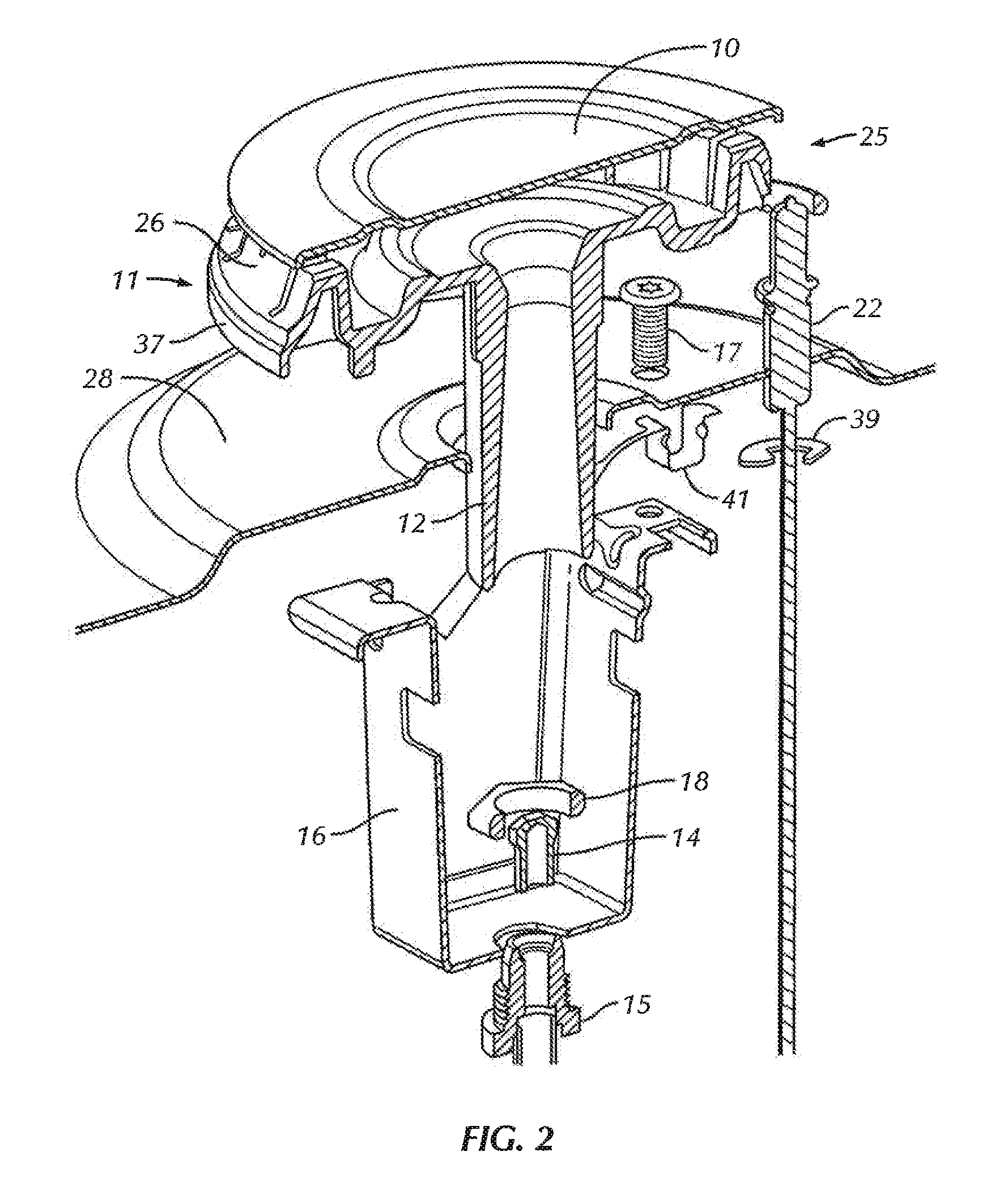
[0028]FIG. 1 illustrates the burner 25 object of present invention, set over a surface or cover 19, the referred to cover 19 preferably comprises a volcano 28 which is understood as a truncated cone protuberance in a volcano manner over which the burner 25 is placed, in an alternative embodiment of present invention, the cover 19 can be completely smooth, or lacking volcanoes; given this the burner 25 is placed flush in regards to the cover 19; in another alternative embodiment the cover 19 can have crammed recesses in truncated conical shape which can house the burner 25. In either case, over the burner assembly 25 (with or without volcano 28) a gril...


PUM


Abstract

A gas burner comprising a section for mixing combustible gas with air; a cover lid closing the mixing section; and a crenellated wall comprising first segments with a first thickness and one or more second segments with a second thickness greater than the first thickness, the second segment allows the cover lid to be sitting and placed over the wall, and main portholes which are constant for a determined length of said main portholes from an inside towards an outside of the crenellated wall, and near the outside of the crenellated wall, the height of the porthole is decreased by virtue of an α angle; one or more secondary portholes with a size smaller than the main portholes, wherein the at least one secondary porthole has a change in direction in such a way, that the height of the at least one secondary porthole decreases from the inside towards the outside of the crenellated wall according to a β angle until the height of the porthole achieves a constant height near the outside of the wall; and two or more tertiary portholes per each first and second segment with a half cane shape, the diameter of each half cane being equal to the width and depth of said tertiary porthole, wherein said tertiary portholes are of lesser size than the at least one secondary porthole.

Description

FIELD OF THE INVENTION[0001]Present invention lies in the field of gas burners, particularly burners used in household appliance equipment, such as stoves, kitchens or cooking surfaces.BACKGROUND OF THE INVENTION[0002]A great variety of burners can be found in the marketplace for use in household appliances or industrial ones based on an atmospheric Bunsen burner; initially, the main objective of these was to provide a flame which would turn on over the utensils to be heated; achieving this without considering efficiency aspects of the combustibles used in the heating or ecologic oriented aspects, heating speed, the shape of the cooking utensils, among others, through time the design of the burners has evolved towards the solving of the above mentioned aspects.[0003]Currently, a considerable amount of burners for use in household appliances exists in the marketplace; initially, the main objective of these was to provide a flame which would turn on over the utensils to be heated with...

Claims


Application Information

Patent Timeline
IPC IPC(8): F24C3/08F23D14/06
CPCF24C3/085F23D2203/007F23D14/06F23D14/64F23D2900/00003
Inventor CABRERA BOTELLO, ROBERTO
Owner MABE SA DE CV
Why Eureka
Try Eureka