Method and device for the diagnosis of the effectiveness of a catalytic converter

A catalytic converter and efficiency technology, which is applied in the direction of exhaust device, diagnostic device of exhaust treatment device, electronic control of exhaust treatment device, etc., can solve the problem of surge in investment in equipment investment process, etc.

Inactive Publication Date: 2012-06-20
CONTINENTAL AUTOMOTIVE GMBH
View PDF3 Cites 0 Cited by
  • Summary
  • Abstract
  • Description
  • Claims
  • Application Information

AI Technical Summary

Problems solved by technology

[0007] Furthermore, the known method has the disadvantage that a catalytic converter arranged very close to the engine, for example in the corresponding cylinder head, in the exhaust manifold or directly upstream of the turbocharger, would make additional equipment investment and / or process investment surge

Method used


Image

  • Method and device for the diagnosis of the effectiveness of a catalytic converter
  • Method and device for the diagnosis of the effectiveness of a catalytic converter

Examples


Embodiment Construction

[0031] In all figures, the same components and method steps are uniformly provided with the same reference signs.

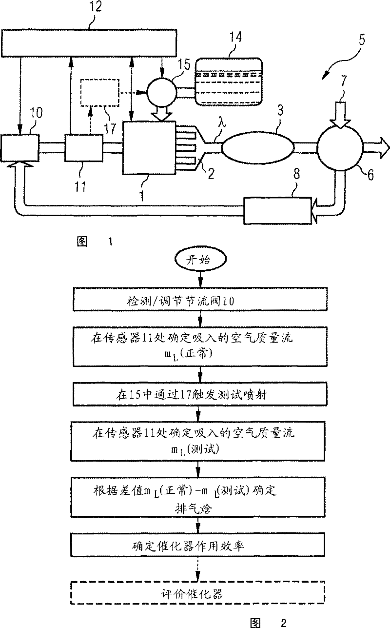
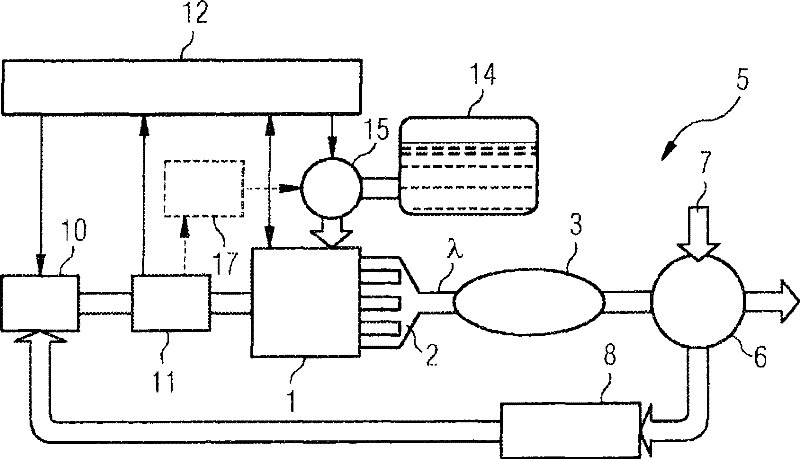
[0032] attached figure 1 A simplified block diagram of the drive system of a motor vehicle is shown with an internal combustion engine 1 , an exhaust gas discharge line 2 and a catalytic converter 3 arranged as close as possible to the engine. In the exhaust system 5 starting from the exhaust passage 2 , a turbocharger 6 is connected downstream of the catalytic converter 3 in the further flow direction. In order to take advantage of the highest possible exhaust gas temperatures, the turbocharger 6 is also arranged as close as possible to the engine and thus causes the fresh air 7 to be precompressed as efficiently as possible. The fresh air 7 pre-compressed by the turbocharger 6 is controlled via a charge air cooler 8 for regulating the air quantity or air mass supplied to the internal combustion engine 1 via a throttle valve 10 . Air quality m L It is detecte...


PUM


Abstract

The present invention relates to a method and a device for the diagnosis of the effectiveness of a catalytic converter in the exhaust gas line of an internal combustion engine when using a very late after injection or secondary injection. In order to provide a sensitive and yet robust diagnostic method while saving costs for additional exhaust gas temperature sensors and with fuel consumption increased only to a minimum extent, said diagnostic method delivering reliable results with only little delay, and a corresponding device which can also easily be used in various concepts for internal combustion engines, it is proposed that an increased compressor output, caused in the course of the test injection, of an exhaust gas turbocharger (6) used downstream of the catalytic converter (3) produce a higher charge pressure or a marked increase in the air mass flow (mL), such that the effectiveness of the catalytic converter (3) is determined from a change in the intake air quantity of the internal combustion engine (1).

Description

technical field [0001] The invention relates to a method and a device for diagnosing the performance of an exhaust gas catalytic converter in an exhaust system of an internal combustion engine, in which a very late post-injection or secondary injection is used. Background technique [0002] It is known from the prior art to arrange the post-injection so that the injected fuel is ignited again and increases the temperature of the exhaust gases by combustion in the expansion phase. As a result, according to document EP 0 621 400 B1, a catalytic converter arranged in the exhaust system is quickly heated from a cold state to operating temperature. [0003] It is known from DE 10061796 A1 that the response behavior of a downstream exhaust gas turbocharger can be improved by specially setting the reinjection in that the fuel injected afterward is converted substantially only in the region of the catalytic converter and there The temperature and enthalpy of the exhaust gas are sig...

Claims


Application Information

Patent Timeline
Patent Type & Authority Patents(China)
IPC IPC(8): F02D41/14F02D41/18F02D41/40F01N11/00
CPCF02D41/0007Y02T10/44F01N11/00F02D41/405F01N3/2033Y02T10/26F02D41/1495Y02T10/47F02B37/00Y02T10/144F01N2550/02F02D41/18Y02T10/12Y02T10/40
Inventor R·迪伊特H·-P·拉布J·拉德茨基
Owner CONTINENTAL AUTOMOTIVE GMBH
Why Eureka
Try Eureka