Method for improving engine starting

a technology for engine starting and engine control, applied in the direction of electric control, ignition automatic control, instruments, etc., can solve the problems of increasing the air mass flow of the engine, affecting the operation of vacuum actuators, increasing the fuel consumption, etc., to reduce tailpipe emissions, reduce fuel consumption, and efficiently convert regulated gases

Active Publication Date: 2013-06-13
FORD GLOBAL TECH LLC
View PDF27 Cites 21 Cited by
  • Summary
  • Abstract
  • Description
  • Claims
  • Application Information

AI Technical Summary

Benefits of technology

[0002]An engine having an exhaust after treatment system may produce its highest concentration of regulated tailpipe exhaust emissions during engine starting when the after treatments system may be operating at a lower level of efficiency. One way to reduce tailpipe emissions is to rapidly heat the exhaust after treatment system so that the exhaust after treatment system may more efficiently convert regulated gases. The exhaust after treatment system may be heated more rapidly via increasing an exhaust mass flow rate to the after treatment system. However, increasing the exhaust gas flow rate beyond what is required for rapid catalyst heating may increase fuel consumption more than is desired. Further, increasing the exhaust mass flow rate may require increasing the engine air mass flow, and increasing the engine air mass flow may interfere with providing vacuum to operate vacuum actuators. In addition, when external loads are applied to the engine, the engine air flow rate (and thus exhaust mass flow rate) may be further increased to compensate for the increased engine load. Consequently, engine exhaust heating rate may be increased as engine load increases while there may be no need or desire to provide higher engine exhaust heating rate.

Problems solved by technology

However, increasing the exhaust gas flow rate beyond what is required for rapid catalyst heating may increase fuel consumption more than is desired.
Further, increasing the exhaust mass flow rate may require increasing the engine air mass flow, and increasing the engine air mass flow may interfere with providing vacuum to operate vacuum actuators.
Additionally, since the engine air mass flow rate is held constant during the engine / exhaust after treatment heating period, additional unrequested heat is not provided by the engine to the exhaust system when limited engine load changes occur.

Method used


Image

  • Method for improving engine starting
  • Method for improving engine starting
  • Method for improving engine starting

Examples


Embodiment Construction

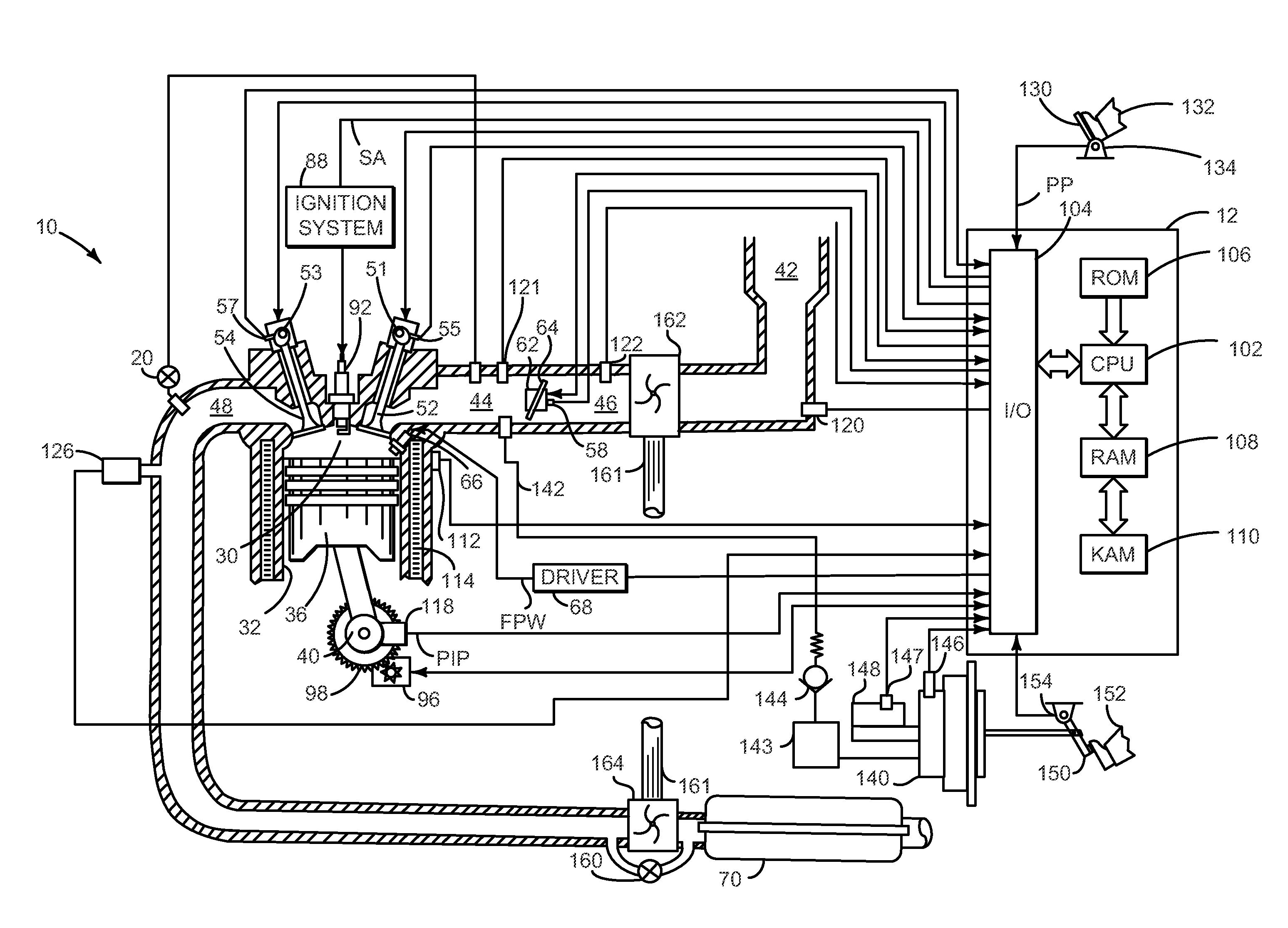
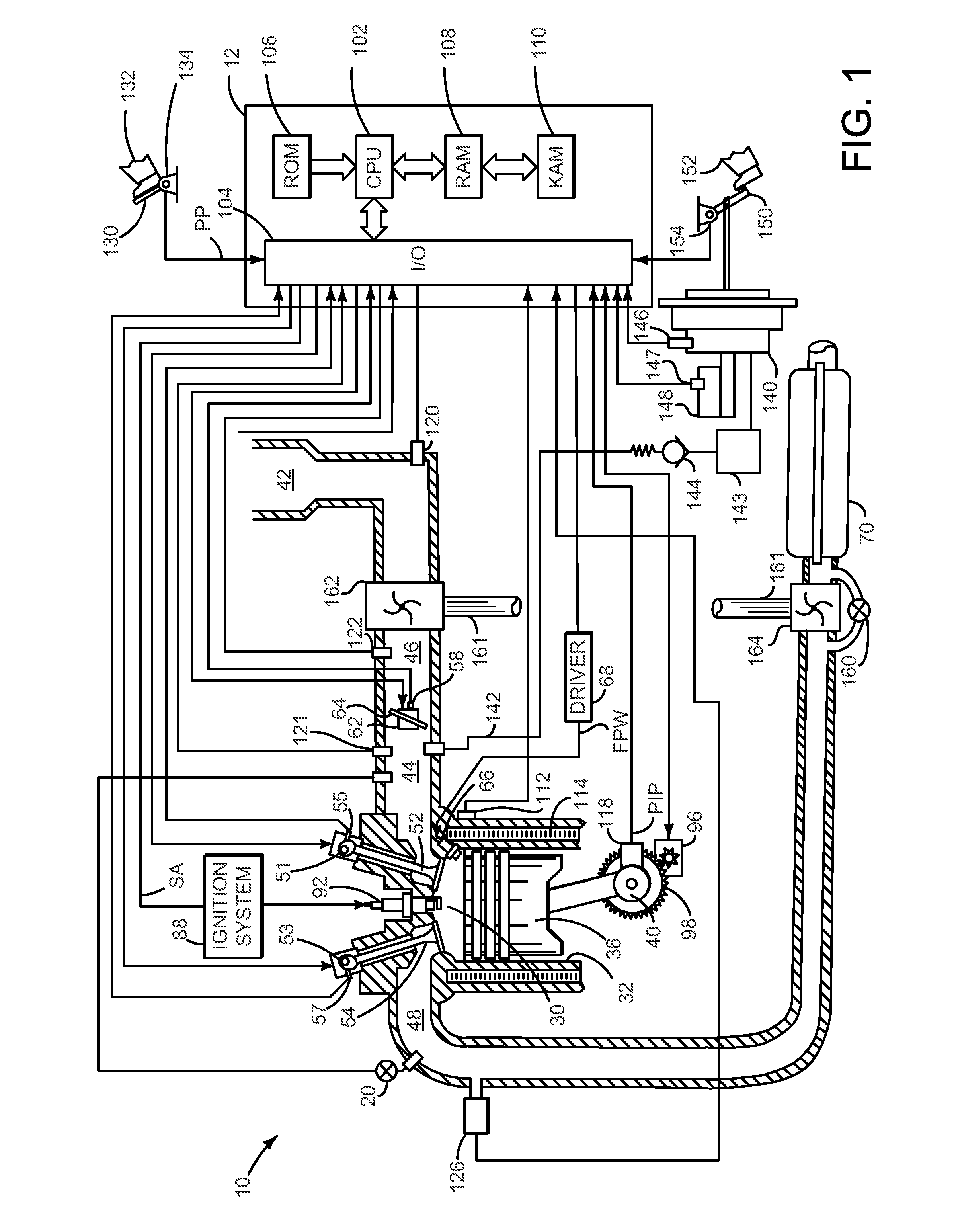
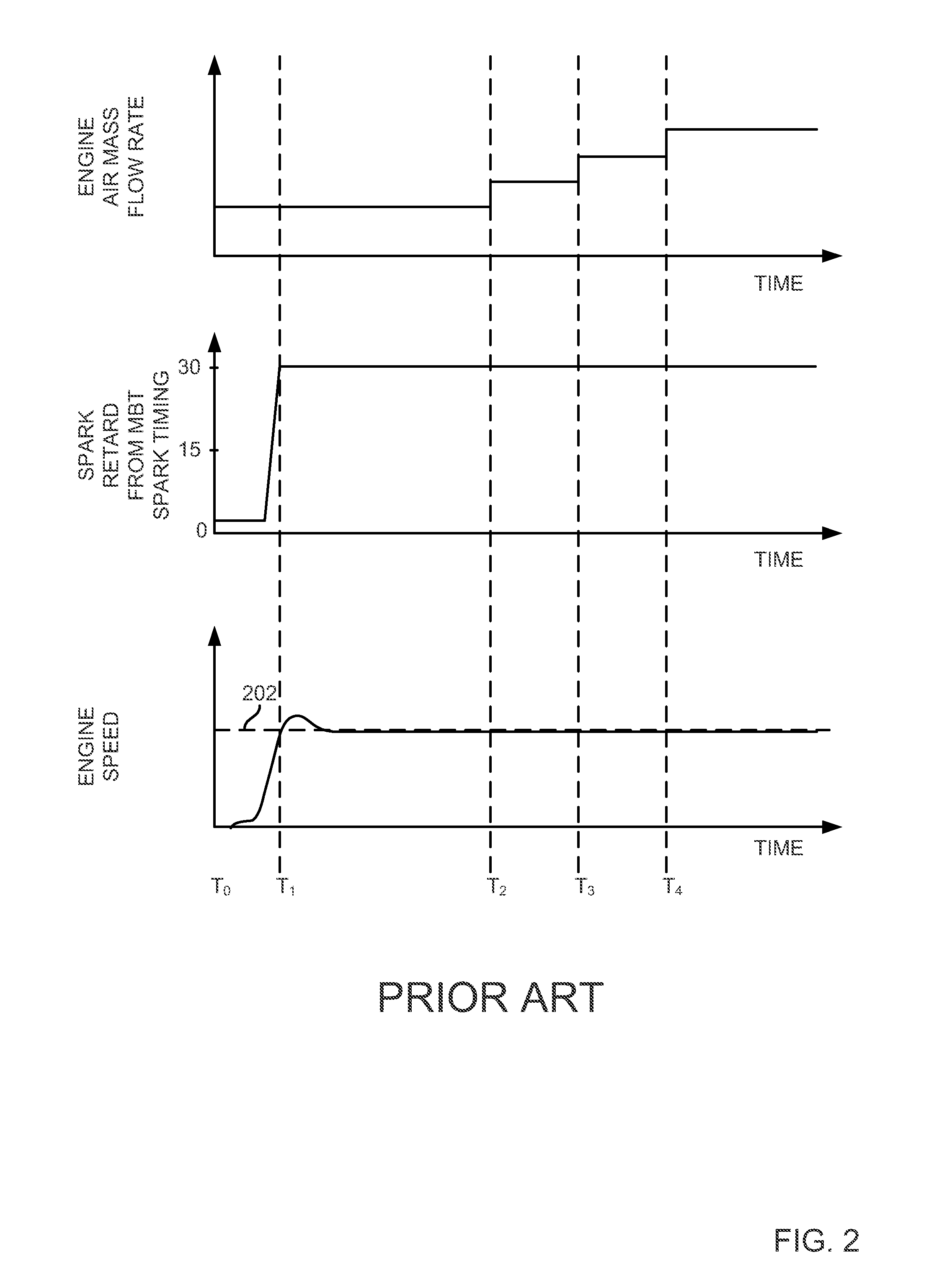
[0015]The present description is related to starting an engine and providing a desired level of heat flux from an engine during an engine warm-up period. In one non-limiting example, the engine may be configured in a system as illustrated in FIG. 1. In this example, the engine is a source of vacuum for operating vacuum consumers (e.g., brake booster, evaporative emission purging, turbo charger waste gate, etc.). FIG. 2 shows prior art method for starting an engine. Example signals of interest when an engine is started via the method described herein are illustrated in FIG. 3. A flowchart of a method to control engine starting is shown in FIG. 4. The method of FIG. 4 describes spark timing adjustments as well as engine air mass flow adjustments during different engine operating conditions. A diagnostic to establish whether or not an engine is operating in a desired manner during a start is illustrated in FIG. 5. The methods of FIGS. 4 and 5 are executable via instructions in the cont...


PUM


Abstract

A method for improving exhaust after treatment initial warm up during engine starting is presented. In one example, the method adjusts an engine air flow amount to a level where a desired substantially constant heat flux is provided by the engine to an exhaust after treatment device. The method may reduce fuel consumption and a need for a vacuum pump to provide vacuum to vacuum consumers of a vehicle during exhaust after treatment heating.

Description

FIELD[0001]The present description relates to a method for controlling an engine during starting. The method may be particularly useful for engines that are boosted to increase engine performance.BACKGROUND AND SUMMARY[0002]An engine having an exhaust after treatment system may produce its highest concentration of regulated tailpipe exhaust emissions during engine starting when the after treatments system may be operating at a lower level of efficiency. One way to reduce tailpipe emissions is to rapidly heat the exhaust after treatment system so that the exhaust after treatment system may more efficiently convert regulated gases. The exhaust after treatment system may be heated more rapidly via increasing an exhaust mass flow rate to the after treatment system. However, increasing the exhaust gas flow rate beyond what is required for rapid catalyst heating may increase fuel consumption more than is desired. Further, increasing the exhaust mass flow rate may require increasing the en...

Claims


Application Information

Patent Timeline
Patent Type & Authority Applications(United States)
IPC IPC(8): F02P5/04F02D45/00
CPCY02T10/46F02D41/0255F02P5/1506Y02T10/42F02D41/0002Y02T10/26F02D37/02Y02T10/12Y02T10/40
Inventor CUNNINGHAM, RALPH WAYNEPURSIFULL, ROSS DYKSTRA
Owner FORD GLOBAL TECH LLC
Why Eureka
Try Eureka