Electric Motor

a technology of electric motors and motors, applied in the direction of windings, magnetic circuit rotating parts, magnetic circuit shapes/forms/construction, etc., can solve the problems of motor eddy current loss, eddy current loss, still be significant, etc., to achieve shortened tooth portion height, increased motor efficiency, and reduced eddy current loss.

Inactive Publication Date: 2015-12-03
JOHNSON ELECTRIC SA
View PDF10 Cites 6 Cited by
  • Summary
  • Abstract
  • Description
  • Claims
  • Application Information

AI Technical Summary

Benefits of technology

[0023]In the motor of the present invention, the motor efficiency is increased by modifying the structure of the stator core to include the inner annular portion, the connecting arms, the outer annular portion, the tooth portions and tips. In the magnetic core, the height of the tooth portions is shortened, such that the magnetic path is shortened and hence the magnetic resistance is reduced. In particular, the ratio of the tooth height L1 of the core laminations of the magnetic core to the circumferential distance L3 between the roots of each two adjacent tooth portions is set to be 1.0-1.3, the

Problems solved by technology

This induction potential produces an eddy current in a transverse section of the stator core, such that the stator core generates heat thus resulting in an eddy current loss of the motor.
The use of laminations reduces the eddy current loss but they can still be significant.
This results in a long magnetic path and hence a high mag

Method used


Image

  • Electric Motor
  • Electric Motor
  • Electric Motor

Examples


Embodiment Construction

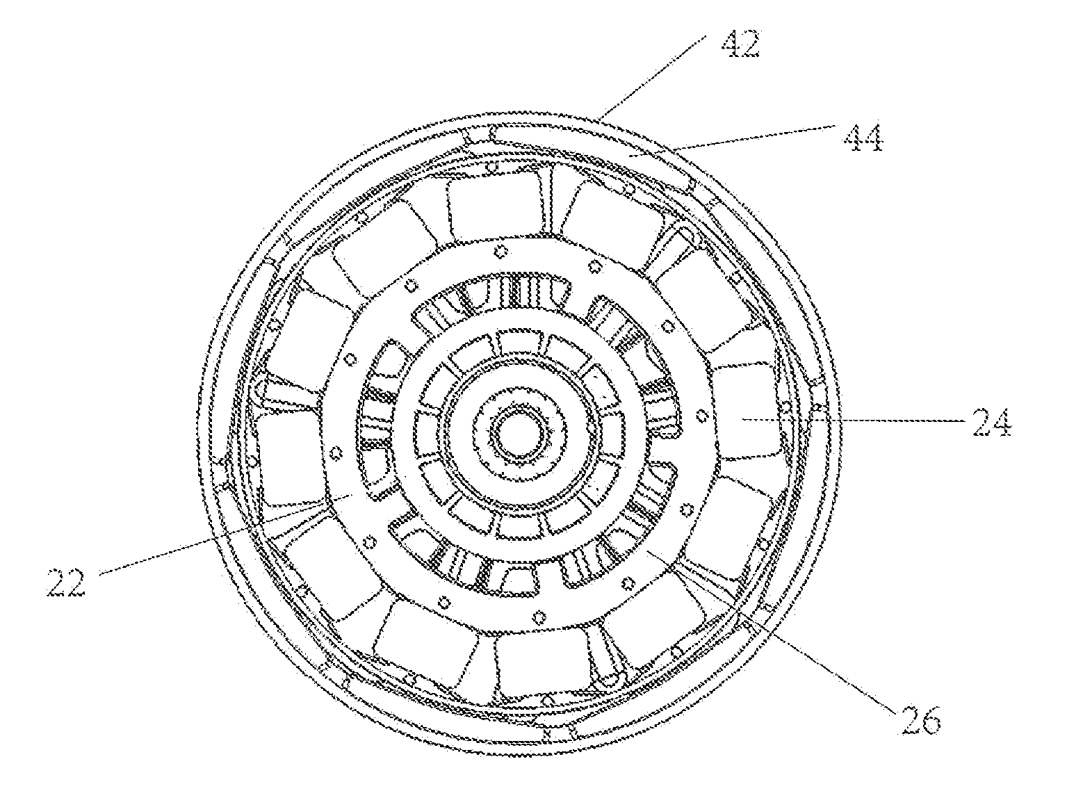
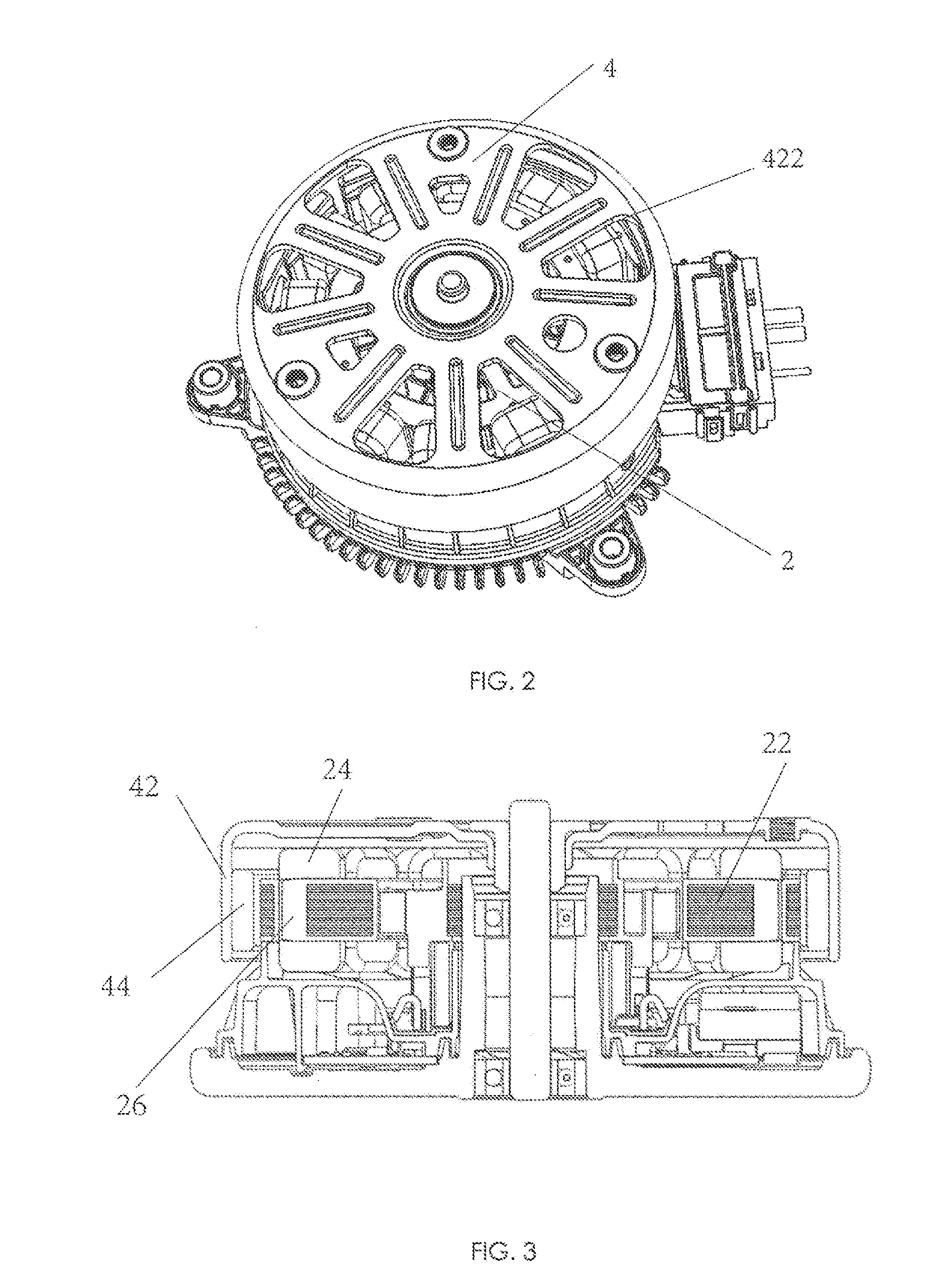
[0040]Referring to FIG. 2 through FIG. 4, a motor in accordance with the preferred embodiment of the present invention is shown. The motor includes a stator 2 and a rotor 4 rotatable relative to the stator 2. The rotor 4 includes an outer housing 42 and a plurality of permanent magnet poles 44 fixed to an inner surface of the outer housing 42. The stator 2 includes a stator core 22, stator windings 24 wound around the stator core 22, and an insulating winding bracket 26 for insulating the stator core 22 from the stator windings 24. The permanent magnet poles 44 surround an outer side of the stator core 22 and stator windings 24.

[0041]Referring also to FIG. 5 through FIG. 7, the stator core of the motor of the present invention has an improved construction. The stator core 22 includes an outer annular portion or ring 221, an inner annular portion or ring 223, a plurality of tooth portions 225 extending radially outwardly from the outer annular portion 221, a plurality of connecting a...


PUM


Abstract

An electric motor has a wound stator and an outer rotor. A core of the stator has outer and inner annular portions. Tooth portions extend radially outwardly from the outer annular portion. Connecting arms interconnect the outer and inner annular portions. The width of the connecting arms is less than the width of the tooth portions. The ratio of tooth height L1 to distance between the roots of adjacent teeth L3 is in the range of 1.0 and 1.3. The ratio of tooth width T3 to L3 is in the range of 0.8 and 1.0. The ratio of tooth length T1 to L3 is in the range of 0.5 and 0.6. The ratio of T3 to outer diameter of the stator core D is in the range of 0.07 and 0.1.

Description

CROSS REFERENCE TO RELATED APPLICATIONS [0001]This non-provisional patent application claims priority under 35 U.S.C. §119(a) from Patent Application No. 201410235916.5 filed in The People's Republic of China on May 29, 2014, the entire contents of which are hereby incorporated by reference.FIELD OF THE INVENTION [0002]This invention relates to an electric motor and in particular, to a brushless motor having an outer rotor.BACKGROUND OF THE INVENTION [0003]Electric motors have a stator and a rotor which is rotatable with respect to the stator. In an outer rotor motor the rotor is disposed around the stator. In a brushless DC motor the rotor has magnetic poles formed or created by one or more permanent magnets, while the stator has windings which form the magnetic poles of the stator. The stator core is a key component for mounting and positioning of the stator windings and providing magnetic flux path for the stator. The stator core is usually formed by a stack of core laminations o...

Claims


Application Information

Patent Timeline
IPC IPC(8): H02K1/18H02K5/20H02K3/34
CPCH02K1/187H02K5/20H02K3/345H02K21/22H02K1/146H02K5/225H02K2213/03H02K5/207H02K1/2791
Inventor JIANG, MAO XIONGZHAO, JIANSUN, GUO WEILI, YONGWANG, YONGZHAO, HONG JIANGLI, YUE
Owner JOHNSON ELECTRIC SA
Why Eureka
Try Eureka