Internal vibration impulsed broadband excitation energy harvester systems and methods

an energy harvester and broadband excitation technology, applied in piezoelectric/electrostrictive/magnetostrictive devices, piezoelectric/electrostriction/magnetostriction machines, electrical equipment, etc., can solve the problem that the type of shock-like inputs is insufficient to fully maximize achieves maximum energy harvesting power generation, easy integration, and high efficiency

Inactive Publication Date: 2015-12-03
WIRELESS SENSOR SOLUTIONS LLC
View PDF3 Cites 20 Cited by
  • Summary
  • Abstract
  • Description
  • Claims
  • Application Information

AI Technical Summary

Benefits of technology

[0008]In the present invention, an alternative method of exciting a cantilevered beam system with shock-like inputs (where shock-like inputs are excitations not continuously fixed at the natural resonant frequency of the vibrational harvester) to the energy harvester device under loading conditions is provided. Normal kinetic motion input sources can produce shock-like input responses such as those due to vibration and jarring. These shocks can be regular in frequency, but not matched to the resonant frequency of the harvester, or variable in frequency and duration. However, these types of shock-like inputs may be inadequate to fully maximize energy harvesting power generation, because they are not matched to the natural resonant frequency of the resonator beam of the energy harvester device and do not enable it to enter a resonant mode of operation. Therefore, the present invention is directed to an energy harvester system that generates excitation of the harvester device under all motion input types to maximize power generation. The

Problems solved by technology

However, these types of shock-like inputs may be inadequate to fully maximize energy harvesting power generation, because they are not matched t

Method used


Image

  • Internal vibration impulsed broadband excitation energy harvester systems and methods
  • Internal vibration impulsed broadband excitation energy harvester systems and methods
  • Internal vibration impulsed broadband excitation energy harvester systems and methods

Examples


example 1

Power Output of an Internal Vibration Impulsed Broadband Excitation Energy Harvester System

[0104]An energy harvester device having a resonator beam with a frequency of 600 Hz experienced an impulse of 18.5 G with a 1 ms base width. The resulting DC power output was 1 μW. The same energy harvester device was then put into a housing comprising internal walls surrounding at least a portion of the energy harvester device. A metal spring supported the energy harvester device within the housing. The system was subjected to the same impulse (18.5 G), causing the internal walls of the housing to contact the energy harvester device multiple times and the resulting DC power output observed was 9 μW.


PUM


Abstract

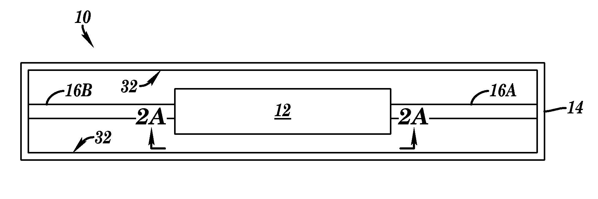
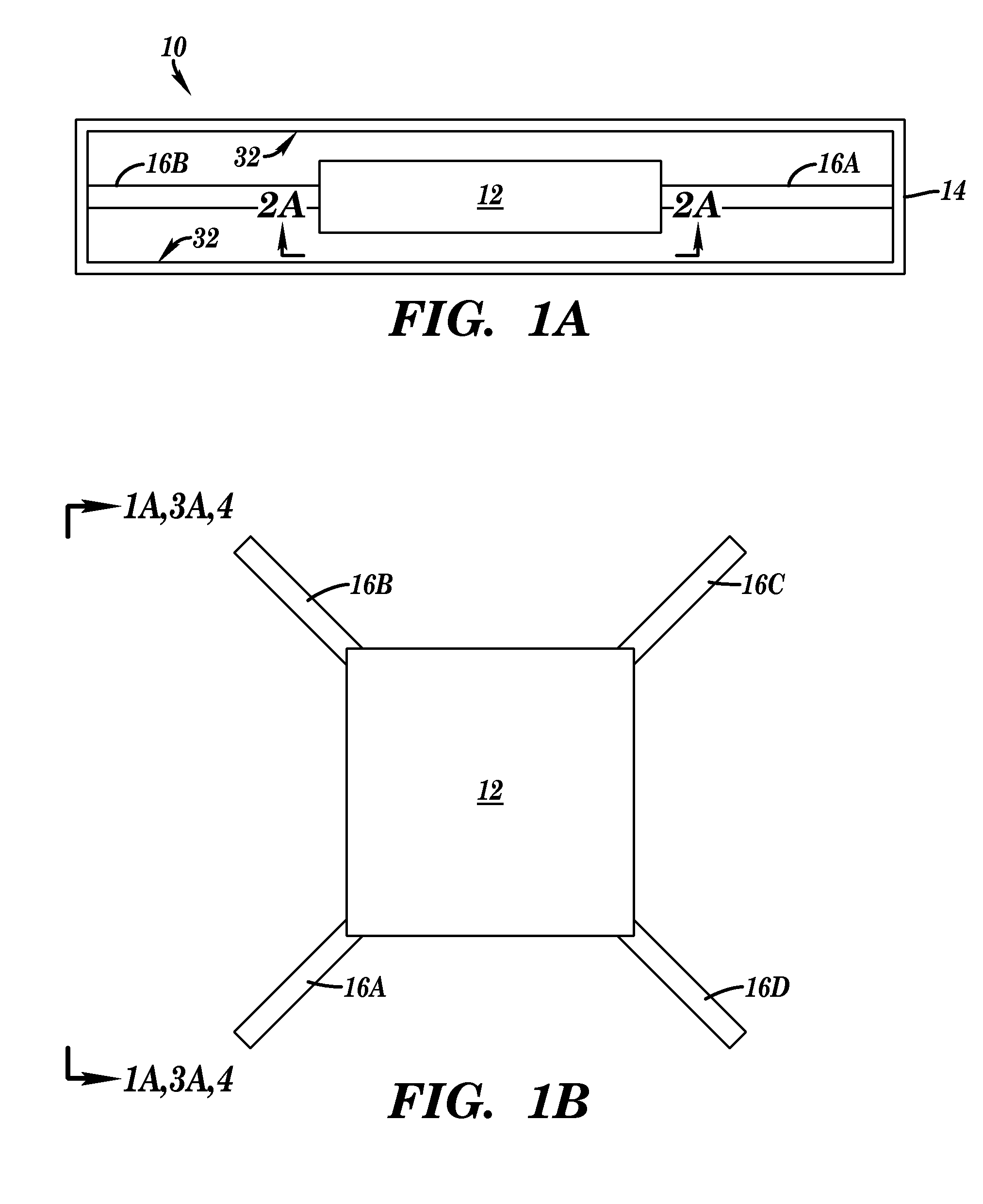
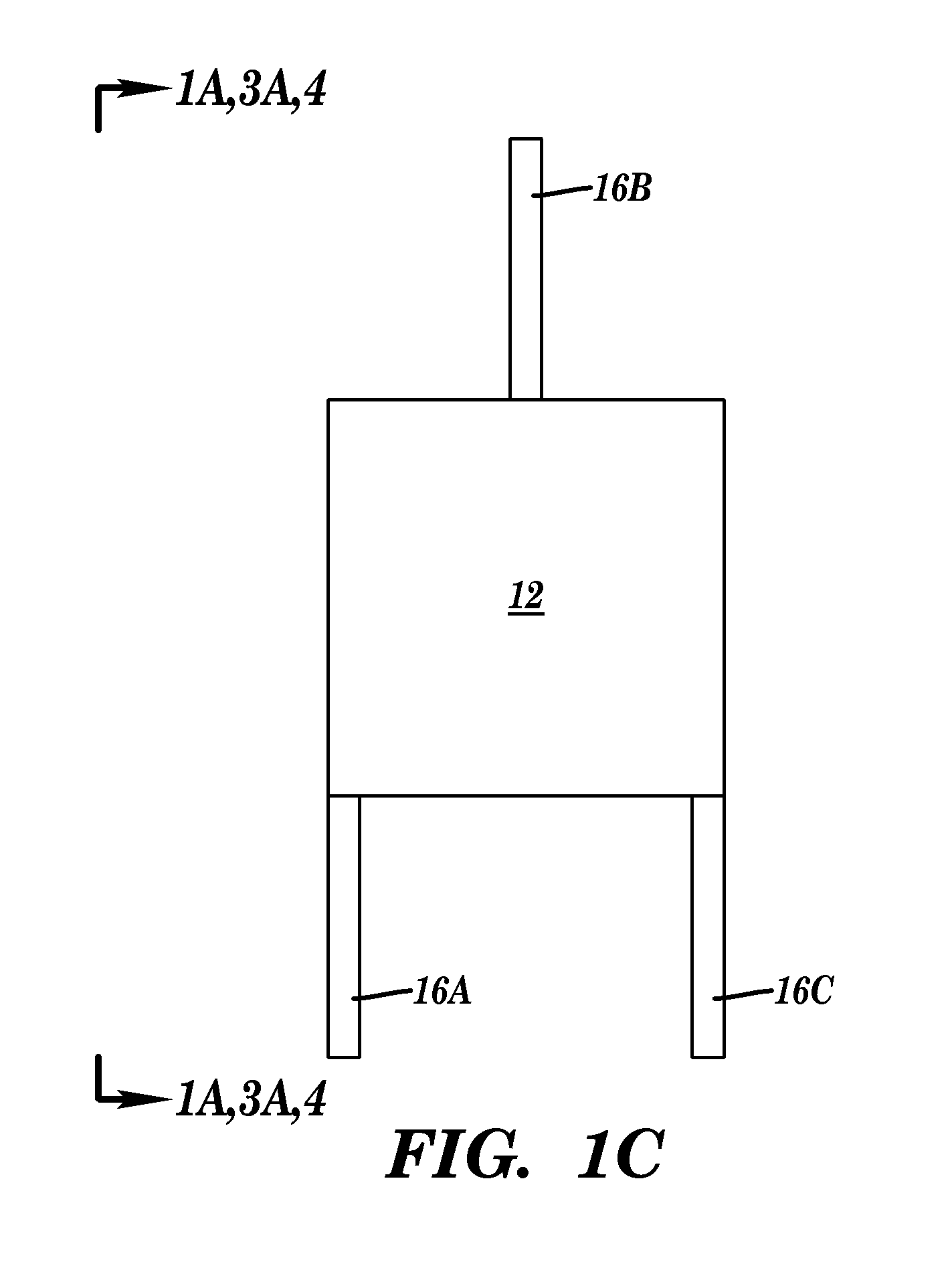
The present invention relates to an energy harvester system. The energy harvester system includes an energy harvester device, a housing comprising internal walls surrounding at least a portion of the energy harvester device, and a flexible supporting structure supporting the energy harvester device within the housing. Movement of the housing causes the internal walls of the housing, or structures connected to the internal walls, to contact the energy harvester device, whereby the flexible supporting structure and the energy harvester device move such that the energy harvester device contacts the internal walls or structures connected to the internal walls at least one additional time (or multiple times), thereby producing energy. Also disclosed is a system comprising an electrically powered apparatus and the energy harvester system of the present invention electrically coupled to the apparatus. The present invention further relates to a method of powering an electrically powered apparatus with the energy harvester system of the present invention.

Description

FIELD OF THE INVENTION[0001]The present invention relates to internal vibration impulsed broadband excitation energy harvester systems and methods of their use.BACKGROUND OF THE INVENTION[0002]Vibrational energy harvester devices offer electrical power generation in environments that lack light, air movement, and temperature gradients. Instead, vibrations and or movements, e.g., emanating from a structural support, which can be in the form of either a vibration at a constant frequency, or an impulse vibration containing a multitude of frequencies can be scavenged (or harvested) to convert movement (e.g., vibrational energy) into electrical energy. One particular type of vibrational energy harvester utilizes resonant beams that incorporate a piezoelectric material that generates electrical charge when strained during movement of the beams caused by ambient vibrations (driving forces), such as that described in U.S. patent application Ser. No. 14 / 173,131 to Vaeth et al.[0003]Improveme...

Claims


Application Information

Patent Timeline
IPC IPC(8): H02N2/18
CPCH02N2/181H02N2/188H10N30/306
Inventor ANDOSCA, ROBERT G.ANDOSCA, JOHNWU, JUNRU
Owner WIRELESS SENSOR SOLUTIONS LLC
Why Eureka
Try Eureka