Radio frequency heating apparatus

a heating apparatus and radio frequency technology, applied in the field of radio frequency heating apparatus, can solve problems such as inhibiting synchronisation, and achieve the effect of reducing manufacturing costs and cheap cabling

Active Publication Date: 2015-12-03
AMPLEON NETHERLANDS
View PDF1 Cites 44 Cited by
  • Summary
  • Abstract
  • Description
  • Claims
  • Application Information

AI Technical Summary

Benefits of technology

[0011]By distributing the radiation generating components of an RF heating apparatus in a plurality of channels, each channel having its own frequency synthesiser which uses a common phase reference signal, greater control over the radiation introduced into the cavity of the apparatus may be provided. For example, the components of each channel may be located within the apparatus with a high degree of flexibility. For instance, embodiments of this invention may allow the components of the channels, such as the power amplifiers, to be placed close to each antenna. This is in contrast to conventional devices in which the location of the radiation generating components may be limited by the need to provide long, lossy distribution paths which can also inhibit synchronisation. The common phase reference signal may, in some examples, be distributed using relatively cheap cabling while still allowing for phase distribution between the frequency synthesisers.
[0012]In some examples, the channels (e.g. the frequency synthesisers thereof) may be controlled independently. This may allow fine tuning of the RF radiation that is introduced into the cavity.
[0017]A frequency of the common phase reference signal may be lower than a frequency of the RF radiation generated by the channels. For example, the common phase reference signal may be in the range 1-100 MHz. A low frequency common phase reference signal may be up converted to a higher frequency by each channel for generating the RF radiation. Distribution of a low frequency common phase reference signal may allow relatively cheap cabling to be used, reducing manufacturing costs.
[0018]The RF heating apparatus may be provided with control circuitry. The control circuitry may be operable independently to control each of the plurality of channels to vary at least one of a frequency, phase and amplitude of the RF radiation generated by each respective channel. This may allow for close control over the RF radiation introduced into the cavity.

Problems solved by technology

This is in contrast to conventional devices in which the location of the radiation generating components may be limited by the need to provide long, lossy distribution paths which can also inhibit synchronisation.

Method used


Image

  • Radio frequency heating apparatus
  • Radio frequency heating apparatus
  • Radio frequency heating apparatus

Examples


Embodiment Construction

[0036]Embodiments of the present invention are described in the following with reference to the accompanying drawings.

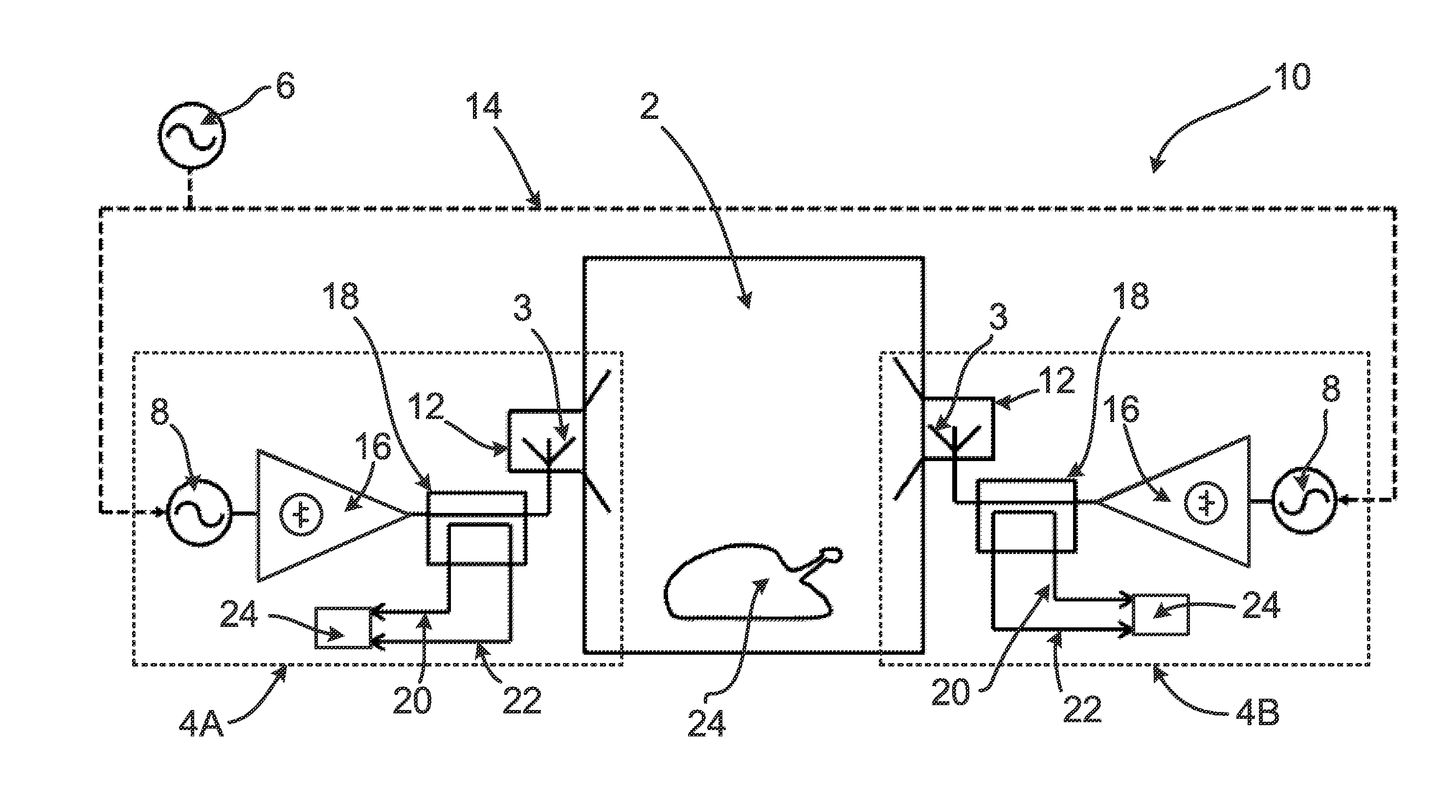
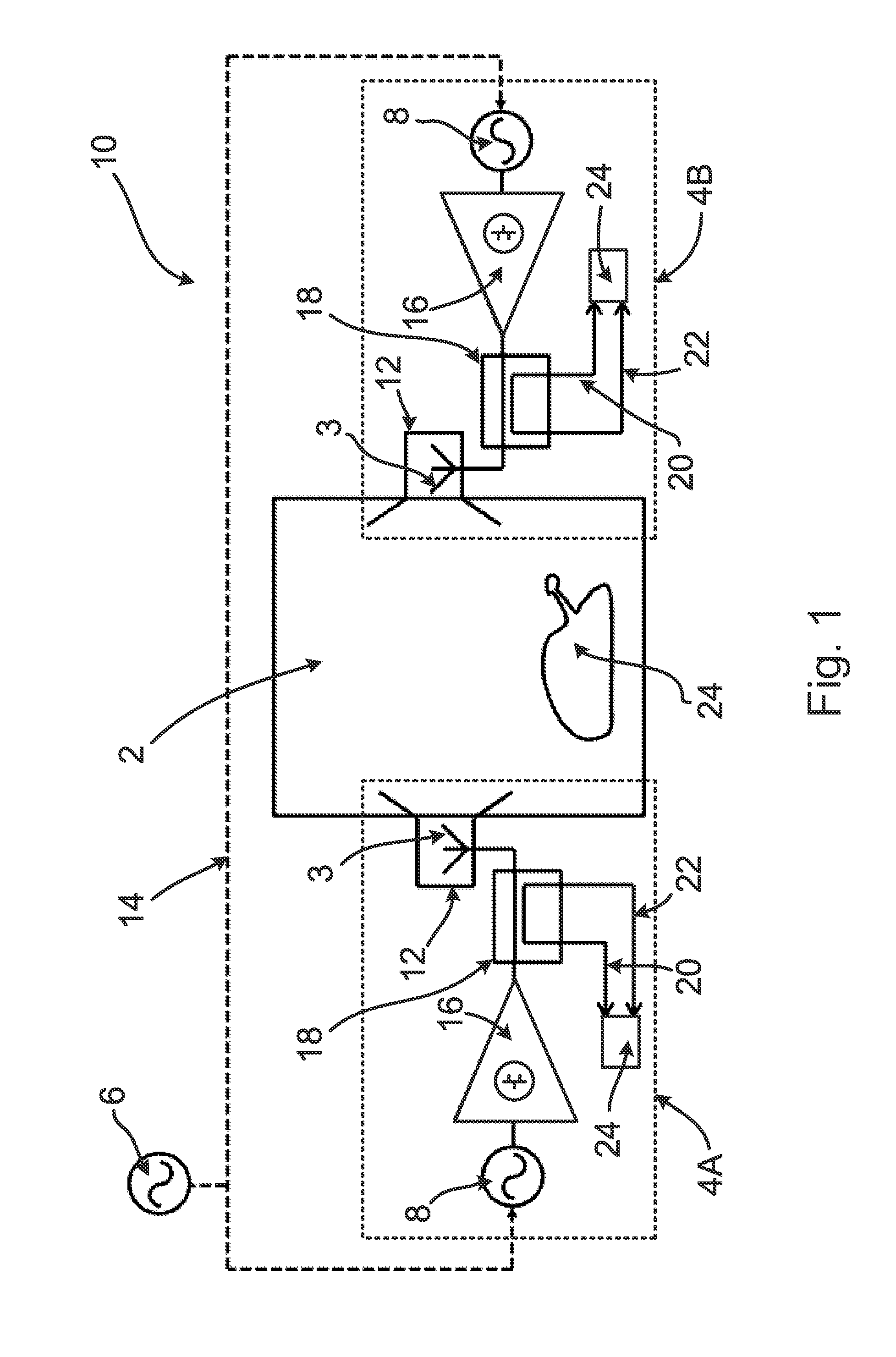
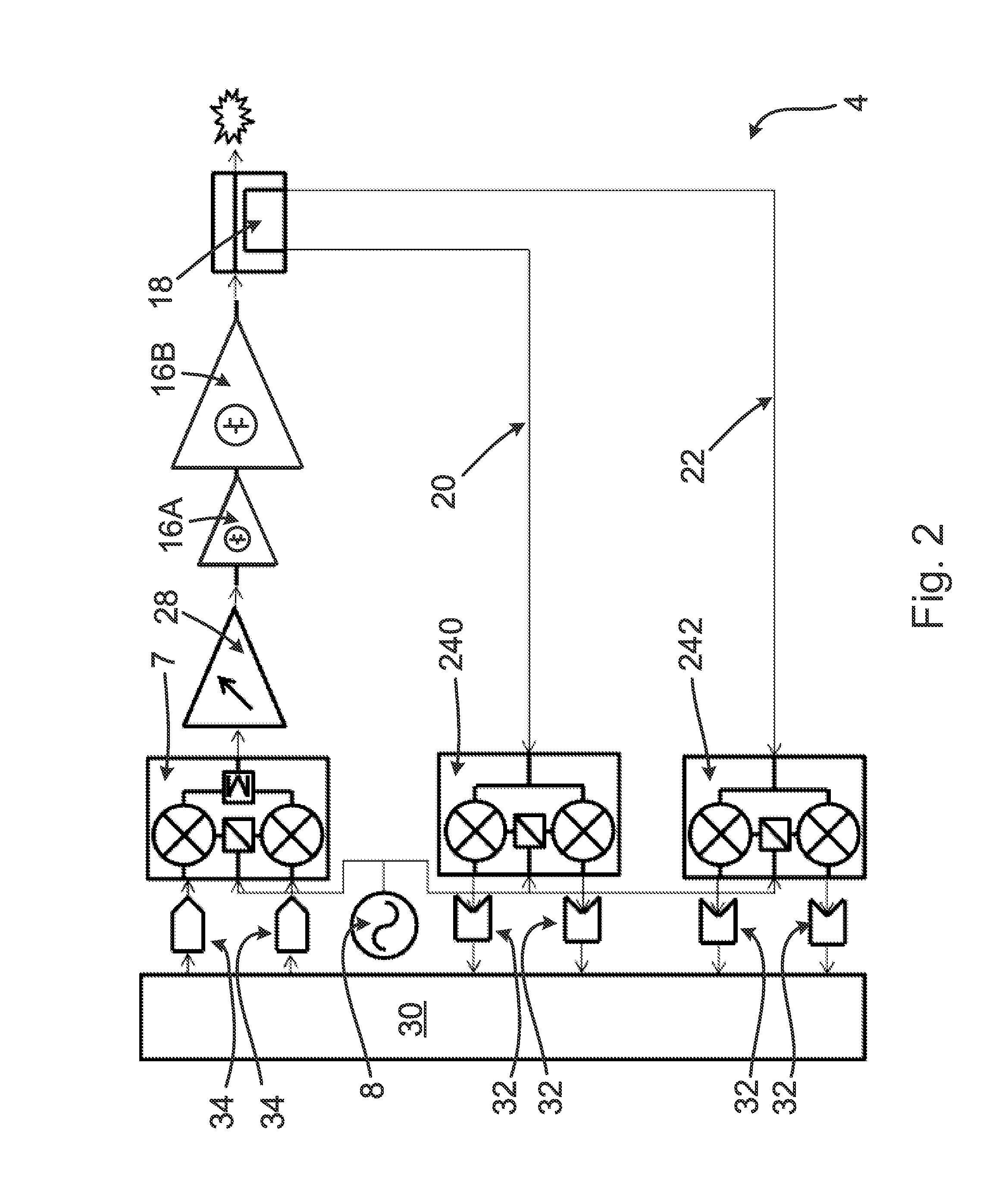
[0037]Embodiments of this invention can provide a radio frequency (RF) heating apparatus in which at least some of the components for generating the RF radiation are distributed into a plurality of separate channels, each channel having its own frequency synthesiser. This separation of the radiation generating components into separate channels can, in some embodiments, allow each channel to be controlled separately (for example, allowing for individual frequency, amplitude and / or phase control). Also, embodiments of this invention provide a radio frequency heating apparatus in which each channel is operable to make use of a common phase reference signal for generating the RF radiation. The common phase reference signal can be used to synchronise the frequency synthesisers of each channel in terms of frequency and / or phase. In some embodiments, the common phase refere...


PUM


Abstract

A radio frequency (RF) heating apparatus and a microwave oven comprising an RF heating apparatus. The apparatus includes a cavity for receiving an object to be heated. The apparatus also includes a plurality of channels for generating RF radiation to be introduced into the cavity. Each channel includes a frequency synthesiser, a power amplifier and an antenna. Each channel is operable to use a common phase reference signal for generating the RF radiation. Each channel may be controllably operable to generate RF radiation having different, respective frequency spectra. Forward and reverse signal detection circuitry may be provided that is operable to determine amplitude, frequency and / or phase information relating to RF radiation in the cavity. This information may be used for adaptively controlling the RF radiation generated by each channel.

Description

FIELD OF THE INVENTION[0001]This invention relates to a radio frequency (RF) heating apparatus. This invention also relates to a microwave oven comprising an RF heating apparatus.BACKGROUND OF THE INVENTION[0002]Conventional radio frequency (RF) heating devices, such as domestic or industrial microwave ovens, use a magnetron to generate RF radiation. Typically, these devices produce radiation at a single frequency or pseudo-randomly within a specific frequency band. These devices are also bulky and are limited with respect to the degree of controllability they provide over the radiation that is introduced into the cavity in which an object is to be heated (e.g. food).[0003]More recently, devices which generate RF radiation using solid state semiconductor components have been proposed. Some conventional devices use a power divider architecture that employ multiple paths of a phase coherent signal for amplification and delivery to a cavity (e.g. see EP 2,182,774 A1 and EP 2,205,043 A1...

Claims


Application Information

Patent Timeline
Patent Type & Authority Applications(United States)
IPC IPC(8): H05B6/68H05B6/64
CPCH05B6/6402H05B6/686H05B6/705H05B6/72Y02B40/00
Inventor WESSON, ROBINWILLIAMS, ROGER
Owner AMPLEON NETHERLANDS
Why Eureka
Try Eureka