Ventricularly-anchored prosthetic valves

a prosthetic valve and ventricular anchoring technology, applied in the field of valve replacement, can solve the problems of decreased cardiac output and increased total stroke volume, and achieve the effect of facilitating automatic transition and decoupling of pull-wires

Inactive Publication Date: 2015-12-10
CARDIOVALVE LTD
View PDF11 Cites 324 Cited by
  • Summary
  • Abstract
  • Description
  • Claims
  • Application Information

AI Technical Summary

Benefits of technology

[0016]For some applications, one or more forces is measured during implantation, and distributed among various anchoring elements. For some such applications, an intracorporeal spring is used that is extracorporeally observable using imaging techniques. For some such applications, the spring facilitates force distribution.
[0320]subsequently to facilitating deflection of the first arm the first angle, and

Problems solved by technology

Regurgitation of blood from the ventricle into the atrium results in increased total stroke volume and decreased cardiac output, and ultimate weakening of the ventricle secondary to a volume overload and a pressure overload of the atrium.

Method used


Image

  • Ventricularly-anchored prosthetic valves
  • Ventricularly-anchored prosthetic valves
  • Ventricularly-anchored prosthetic valves

Examples


Embodiment Construction

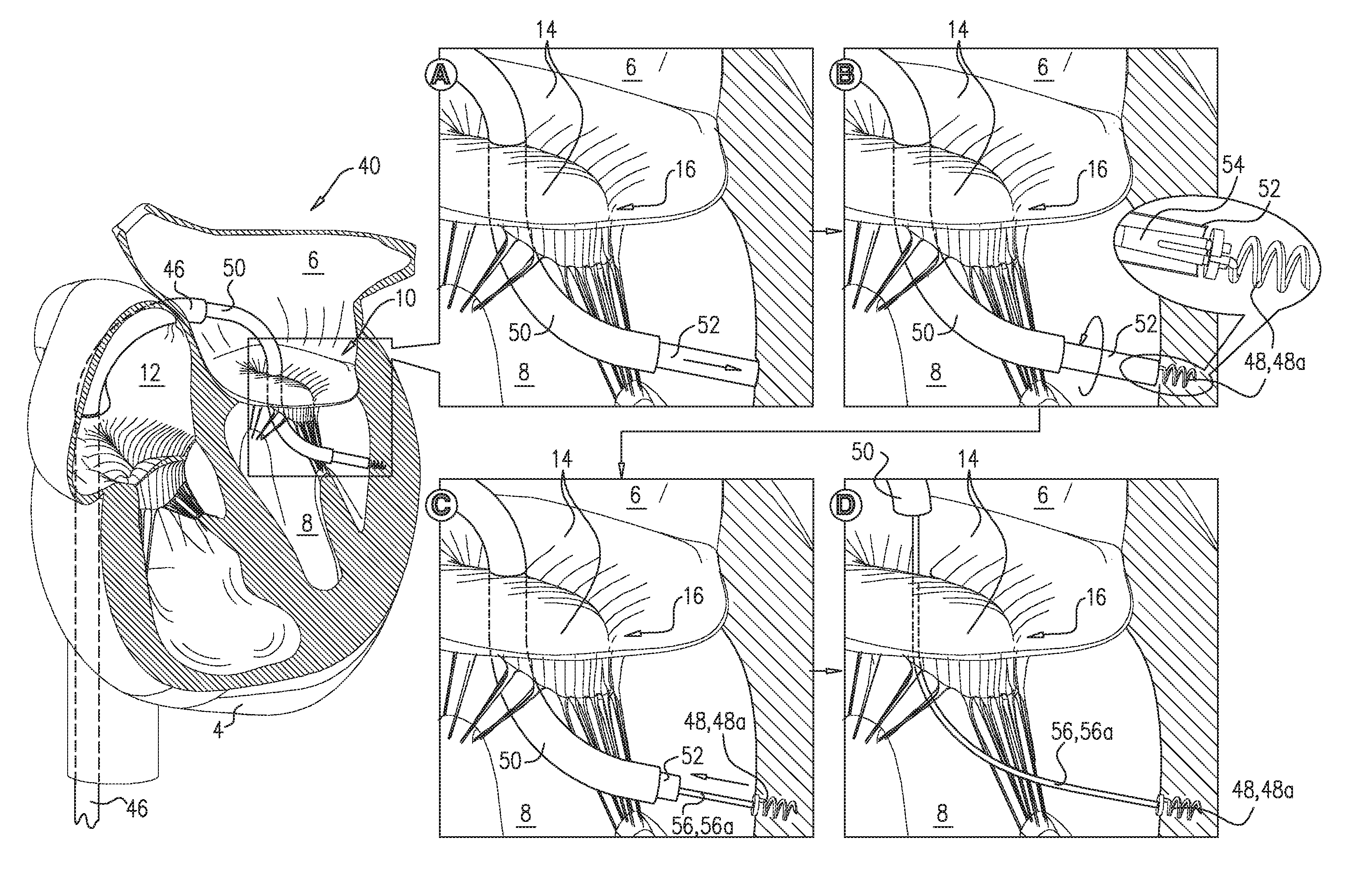
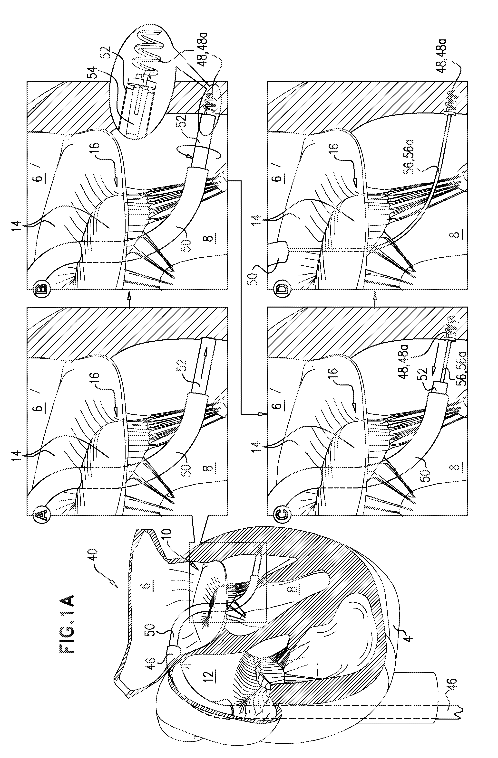
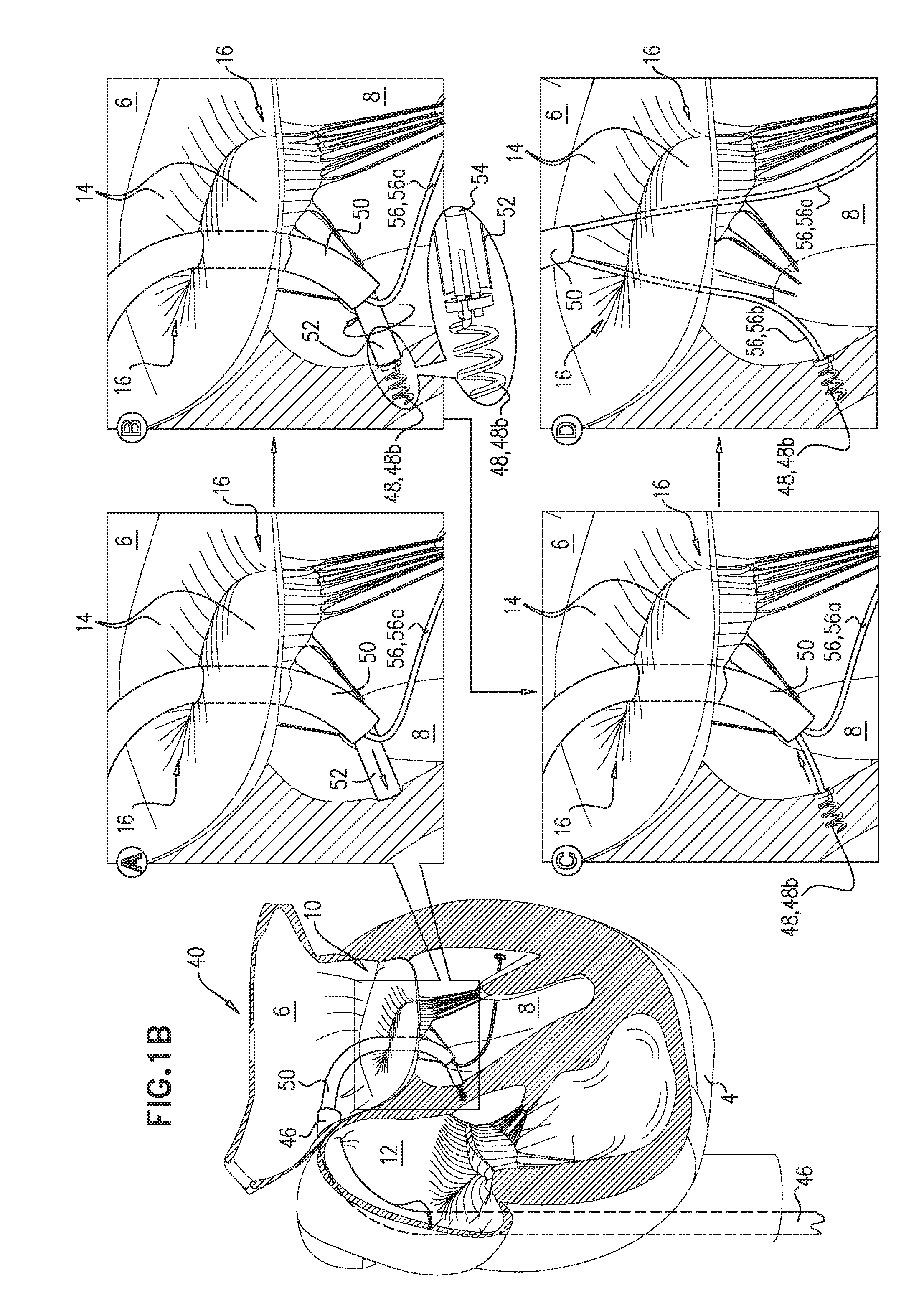
[0378]Reference is made to FIGS. 1A-F, which are schematic illustrations of a system 40 for implanting an upstream prosthetic valve support 42 and a prosthetic valve 44 at a native valve 10 of a heart 4 of a subject, in accordance with some applications of the invention. Typically, applications of the invention are for use with the mitral valve of the subject (that is, native valve 10 comprises the mitral valve of the subject), but it is to be noted that applications of the invention may be used at other heart valves of the subject, such as the tricuspid valve, the aortic valve, or the pulmonary valve, mutatis mutandis.

[0379]Reference is now made to FIGS. 1A-B. A sheath 46 is advanced transluminally (e.g., transfemorally) to right atrium 12 of the heart, and is typically advanced through the fossa ovalis into left atrium 6 of the heart using standard transseptal techniques. For some applications, sheath 46 is steerable. For some such applications, sheath 46 is steerable in two axes....


PUM


Abstract

Apparatus is provided, including: (A) a valve body (204) including a first frame (206) shaped to define a lumen therethrough, and a valve member (205) disposed within the lumen, (B) an upstream support (210), configured to be placed against an upstream surface of a native heart valve, and (C) a flexible sheet (214) that couples the upstream support to the valve body. The valve body has a compressed state in which the first frame has a first diameter, and an expanded state in which the first frame has a second diameter that is greater than the first diameter. The support includes a second frame (212) that has a compressed state, and an expanded state in which the second frame is annular, has an inner perimeter that defines an opening through the second frame, and has an outer perimeter. Other embodiments are also described.

Description

CROSS-REFERENCES TO RELATED APPLICATIONS[0001]The present application claims priority from U.S. provisional patent application 61 / 756,049 to HaCohen et al., filed Jan. 24, 2013, and entitled “Ventricularly-anchored prosthetic valve support”; and U.S. provisional patent application 61 / 756,034 to HaCohen et al., filed Jan. 24, 2013, and entitled “Tissue-engaging elements”, and is related to:[0002]US patent application publication 2012 / 0022639 to Hacohen et al., filed Jul. 21, 2010;[0003]US patent application publication 2012 / 0022640 to Gross et al., filed Feb. 24, 2011;[0004]U.S. patent application Ser. No. 13 / 811,308 to Gross et al., filed Jan. 21, 2013, which published as US 2013 / 0172992;[0005]U.S. patent application Ser. No. 13 / 412,814 to Gross et al., filed Mar. 6, 2012, which published as US 2013 / 0035759;[0006]PCT patent application IL2012 / 000292 to Gross et al., filed Aug. 5, 2012, which published as WO / 2013 / 021374;[0007]PCT patent application IL2012 / 000293 to Gross et al., file...

Claims


Application Information

Patent Timeline
Patent Type & Authority Applications(United States)
IPC IPC(8): A61F2/24
CPCA61F2/2418A61F2/2436A61F2250/0098A61F2220/0075A61F2220/0016A61F2220/0025A61F2/2409A61F2/2427A61F2210/0076
Inventor HAMMER, TALZIPORY, YUVALREICH, TALHERMAN, YARONHACOHEN, GILMILLER, ERANNEEMAN, ROTEMKRUGLOVA, NATALIA
Owner CARDIOVALVE LTD
Why Eureka
Try Eureka