Implant for lower limb amputation

Active Publication Date: 2015-12-10
HOPITAUX UNIVS DE GENEVE
View PDF8 Cites 8 Cited by
  • Summary
  • Abstract
  • Description
  • Claims
  • Application Information

AI Technical Summary

Benefits of technology

[0006]An object of this invention is to provide an implant for lower limb amputation, namely tran

Problems solved by technology

If femoral amputation is more proximal, the Gritti-Stokes amputation technique cannot be performed.
When Gritti-Stokes amputation cannot be implemented, a standard transfemoral amputation is performed; however the distal bony area is too small to receive and allow f

Method used


Image

  • Implant for lower limb amputation
  • Implant for lower limb amputation
  • Implant for lower limb amputation

Examples


Example

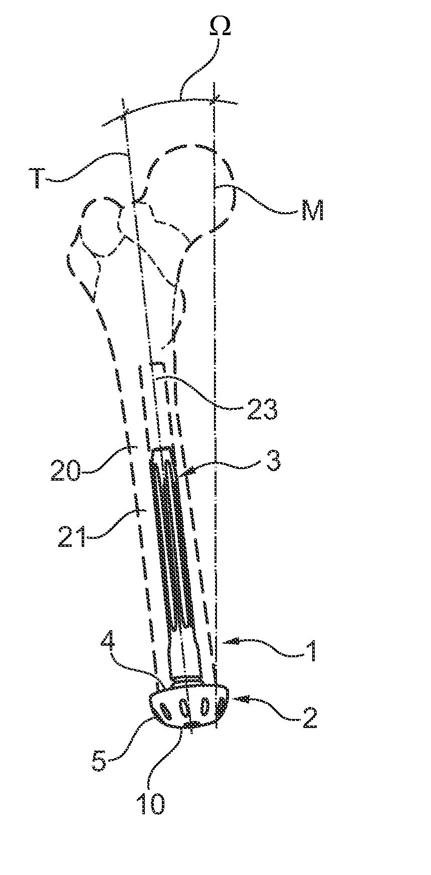
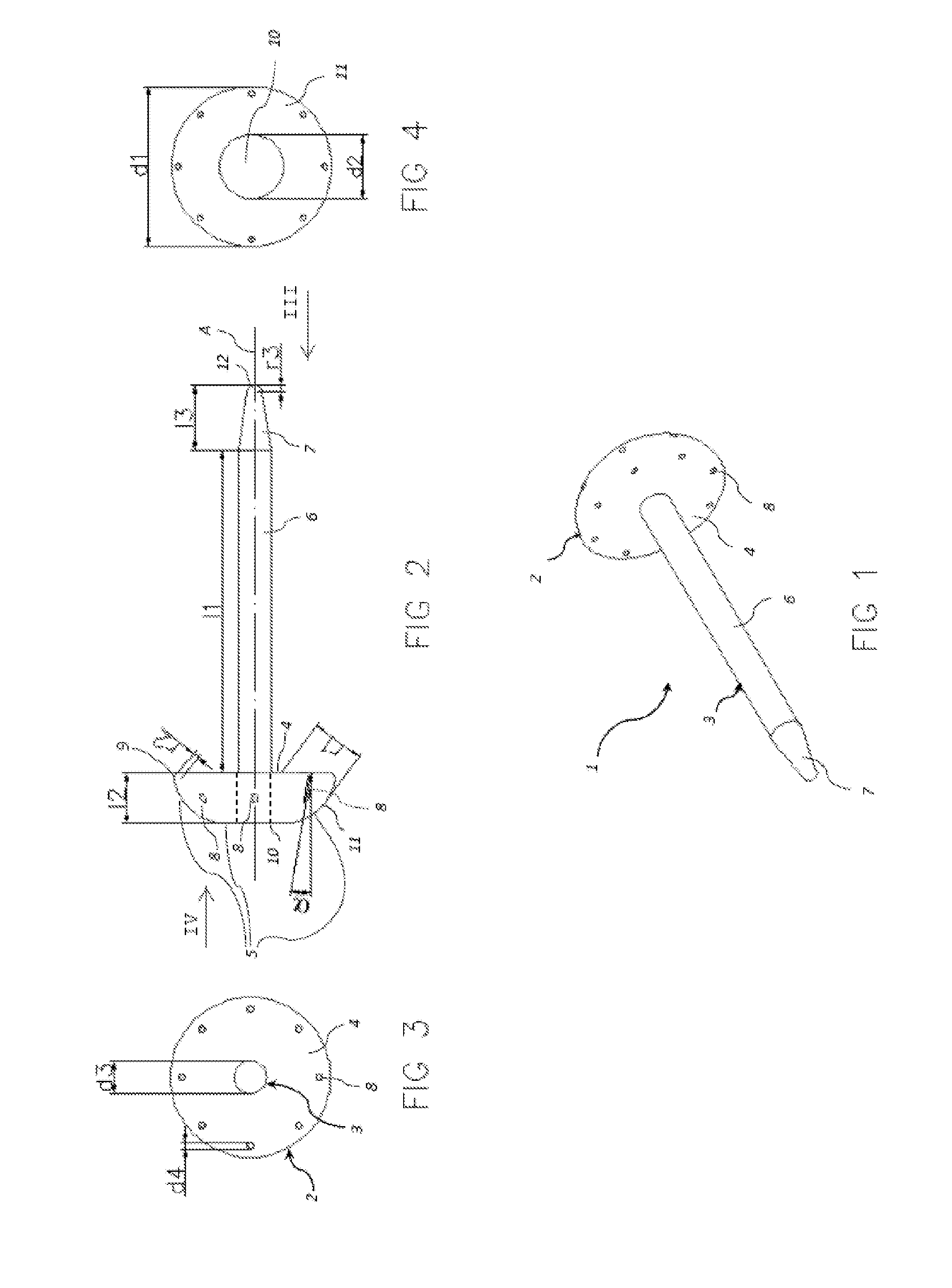
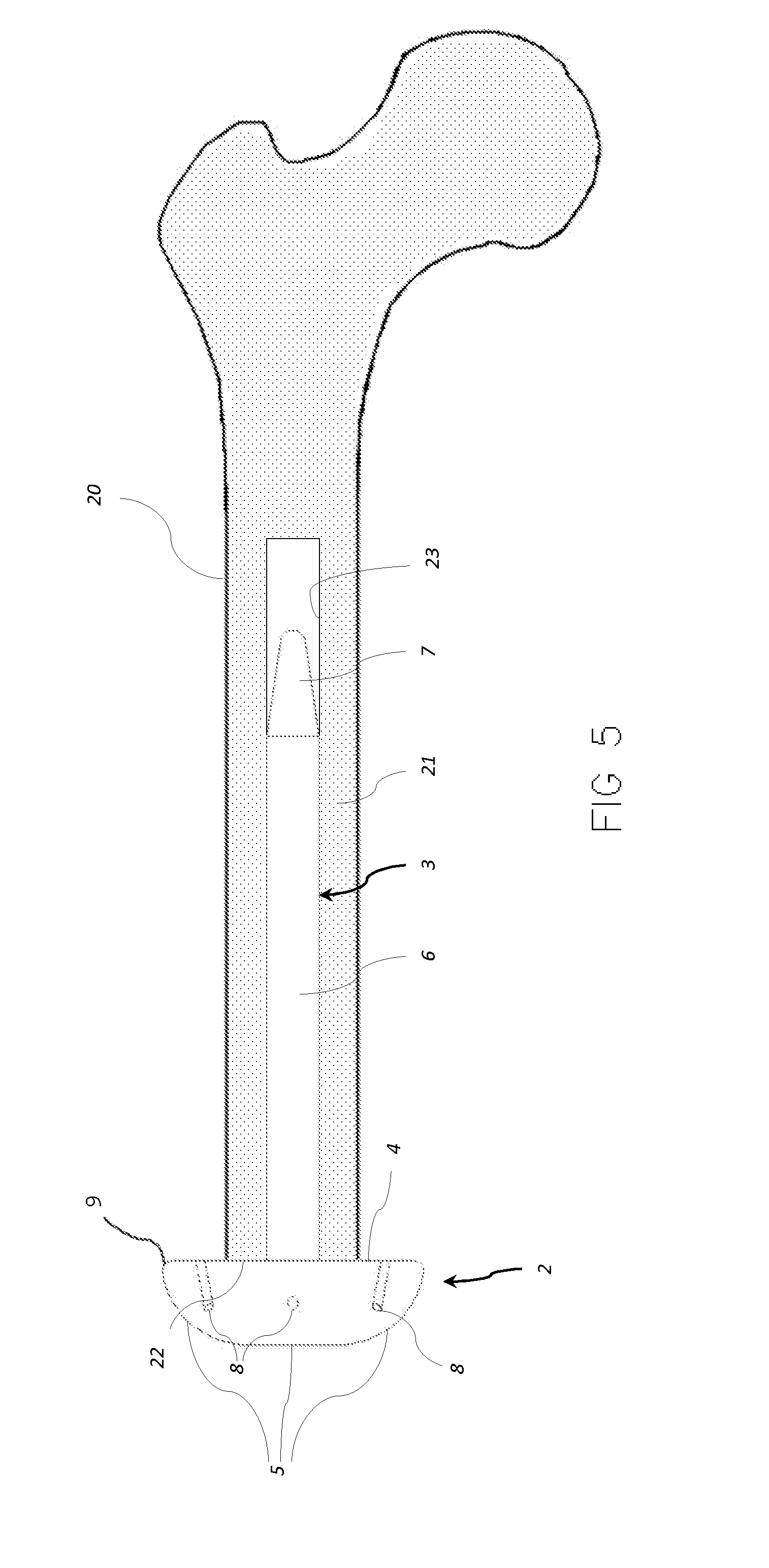
[0050]Referring to the figures, an implant 1 for transfemoral or transtibial amputation is shown, comprising a base 2 and a stem 3 configured to be inserted in a medullary canal 23 of an amputated femur bone, and in a variant, in the medullary canal of an amputated tibia bone. The use of the implant according to this invention is most advantageous for transfemoral amputations, however the advantages it confers are also useful for transtibial amputations. For simplicity, the invention embodiments will be described in relation to the amputation of the femur bone, being understood that the invention may also be used in the case of a transtibial amputation with the same features except for dimensional and angular adjustments taking into account the different anatomy of the above knee and below knee parts and bones of a person's leg.

[0051]The stem 3 is rigidly connected to, and extends from, the base 2. The stem is manufactured as a separate part configured to be assembled to the base an...


PUM


Abstract

Implant for transfemoral or transtibial amputation comprising a stem (3) and a base (2), the base (2) comprising a bone support surface (4) on one side and on an opposite side a soft tissue load bearing surface (5). The stem extends from the base perpendicular to the bone support surface and is configured for insertion in a medullary canal (23) of an amputated bone (20), the bone support surface (4) being configured for abutment against a severed end (22) of said amputated bone. A diameter (d1) of the base is configured to be larger than an average diameter of a shaft (21) of said severed bone, the soft tissue load bearing surface (5) comprising a generally planar or slightly curved central portion (10) and a convexly curved radially outward portion (11) with a curvature greater than the central portion, the central portion (10) being oriented at an angle of between 4° to 8° to the bone support surface.

Description

FIELD OF THE INVENTION[0001]This invention relates to an implant for distal load bearing in amputation of the lower limb, in particular for above knee amputation.BACKGROUND OF THE INVENTION[0002]Amputation of the lower limb is one of the most widely performed surgeries. The levels of amputation which decrease the length of the lower limb may generally be divided into two groups: those for which the bone surface after amputation is large enough to accept the distal delivery and those which require a deferred charge area. For above knee amputation, the weight bearing area is on the ischiatic apophysis. Conventional Gritti-Stokes amputation, which is an alternative to long femoral amputation, provides a terminal support. If femoral amputation is more proximal, the Gritti-Stokes amputation technique cannot be performed.[0003]Two amputation levels can thus be distinguished: (i) those for which the distal end of the bony segment, after amputation, provides an area large enough to receive ...

Claims


Application Information

Patent Timeline
IPC IPC(8): A61F2/78A61F2/28
CPCA61F2/78A61F2/2814A61F2002/7887A61F2002/2892A61F2002/2825
Inventor LACRAZ, ALAIN
Owner HOPITAUX UNIVS DE GENEVE
Why Eureka
Try Eureka