
A label inspection system and method

Active Publication Date: 2015-12-10
CREST SOLUTIONS
View PDF7 Cites 20 Cited by
  • Summary
  • Abstract
  • Description
  • Claims
  • Application Information

AI Technical Summary

Benefits of technology

The patent describes a tool that helps to compensate for movement in label elements as viewed by a scanner. It uses definitions to define search regions that are less tightly defined than the equivalent print regions. The tool also performs automatic normalization of grey scale to compensate for small variations, and uses additional internal images to handle edge effects and mis-registration errors caused by print characteristics. The tool also performs filtering operations to further reduce unimportant small differences. Overall, the tool improves the accuracy and reliability of label printing and detection.

Problems solved by technology

However, these are prone to printing problems.
The labels are subsequently inspected by humans, which is not ideal for this type of methodical, repetitive task.
The problems that are being inspected for may arise from any or a combination of rollers being misaligned slightly, inkjet print head misalignment, ink inconsistencies, paper inconsistencies or incorrect data applied to the label for example.
Also, problems may arise where the label has a thickness greater than that of a single sheet, such as where a small booklet is being printed on its outside cover.

Method used


Image

  • A label inspection system and method
  • A label inspection system and method
  • A label inspection system and method

Examples


Embodiment Construction

[0050]The invention will be more clearly understood from the following description of some embodiments thereof, given by way of example only with reference to the accompanying drawings in which:—

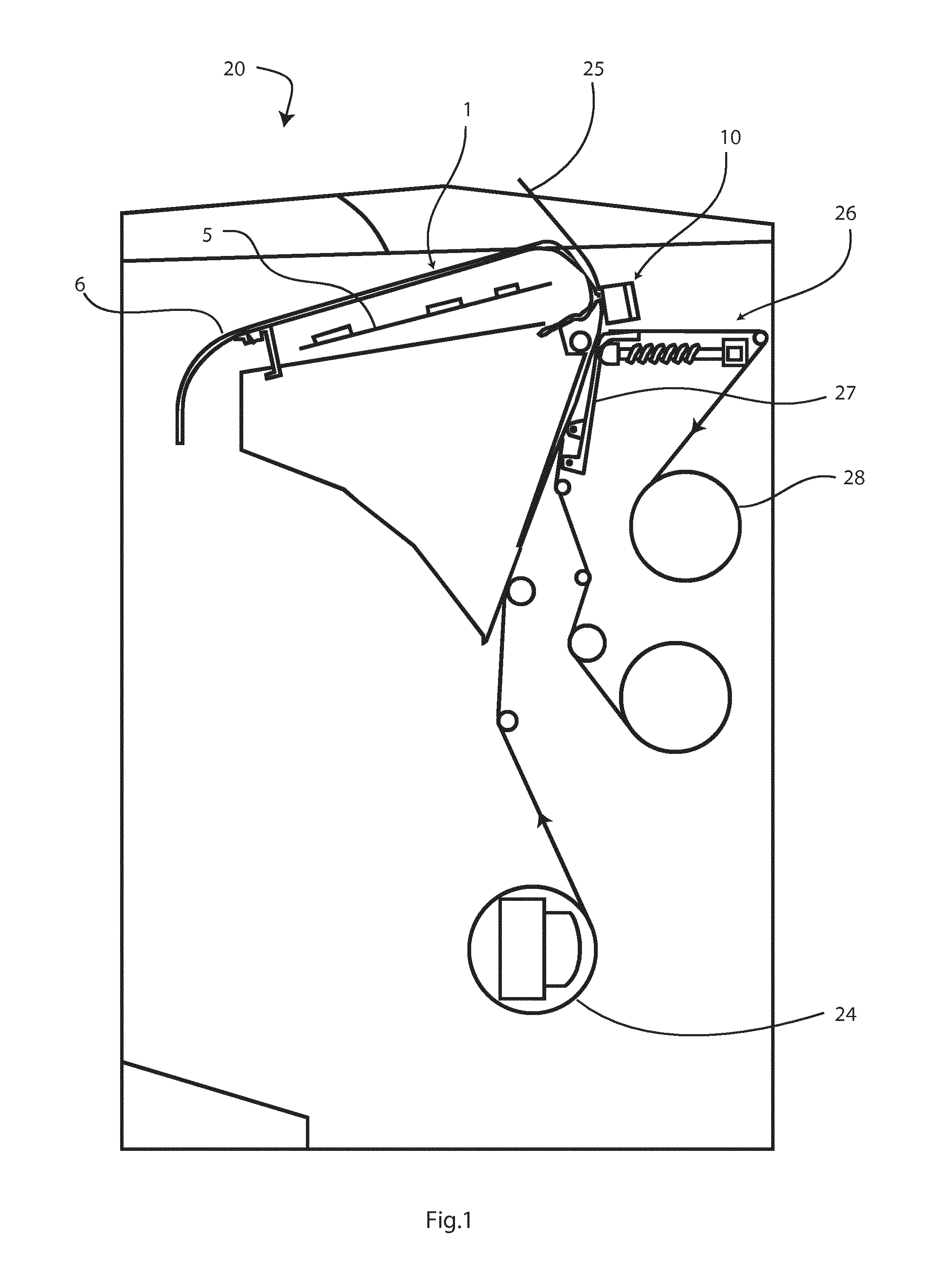
[0051]FIG. 1 is a diagrammatic view of a label test system installed within a printer;

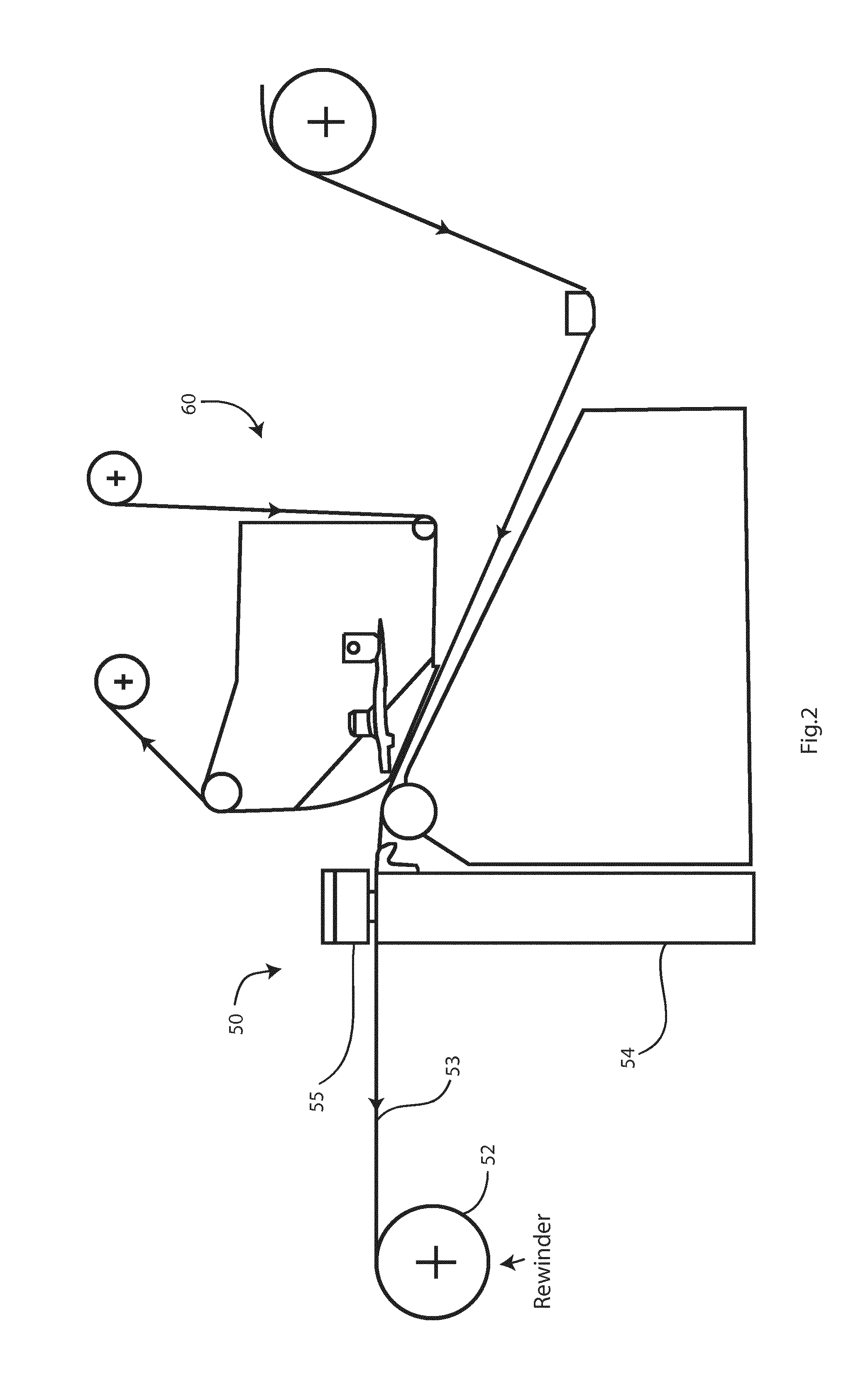
[0052]FIG. 2 is a diagrammatic view of another label test system, mounted on the outside of a printer, and FIG. 3 is a cross-sectional view showing this system in more detail;

[0053]FIGS. 4 to 6 are diagrams for hardware architectures of networks including the test systems in various deployments;

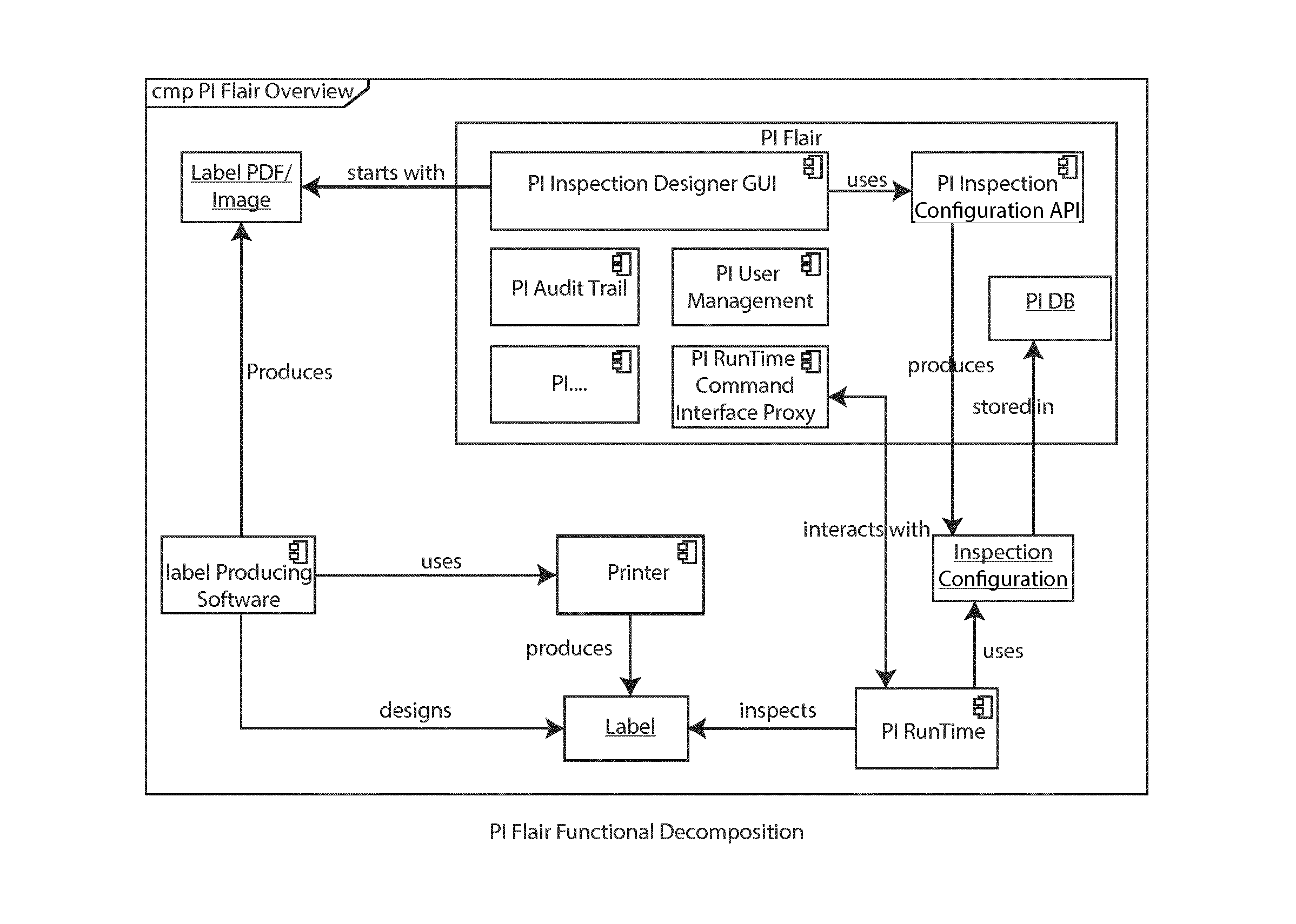
[0054]FIGS. 7 to 9 are block diagrams of the systems, and also showing flows between system components;

[0055]FIG. 10 is a view of a sample label, and FIG. 11 is a view of a calibration label;

[0056]FIGS. 12 to 17 are model diagrams for the system;

[0057]FIG. 18 is a diagram of the hardware architecture of the test system;

[0058]FIGS. 19 to 24 are flow / state diagrams for operation of the test system in various embodiment...


PUM


Abstract

A label inspection system fixture (1) has a scanner and housing (10) for performing full inline or offline inspection within a printer (20). The fixture (1) comprises a control circuit (5) with a processor within a curved guide plate (6). The scanner (10) communicates with the circuit (5), which in turn communicates with a host computer (VPU). The VPU identifies regions in a scanned label and applies to each region an inspection tool associated with that region. At least some of said tools include a stored training image and associated test data defining said regions and inspection criteria for the regions.

Description

[0001]The invention relates to inspection of labels with important information, such as labels for medical, pharmaceutical products or indeed any products for which accuracy of the label is very important. In this specification, the term “label” means any type of label, and substrates with multiple pages such as booklets to be shipped with products.[0002]Typically, the printing is done by industrial thermal printers. However, these are prone to printing problems. The labels are subsequently inspected by humans, which is not ideal for this type of methodical, repetitive task. The problems that are being inspected for may arise from any or a combination of rollers being misaligned slightly, inkjet print head misalignment, ink inconsistencies, paper inconsistencies or incorrect data applied to the label for example. Also, problems may arise where the label has a thickness greater than that of a single sheet, such as where a small booklet is being printed on its outside cover.[0003]The ...

Claims


Application Information

Patent Timeline
IPC IPC(8): G06T7/00H04N1/00G06K15/02
CPCG06T7/001G06K15/024H04N1/00042G06T2207/30176H04N1/00005G06T2207/10008G06T2207/30168H04N1/00082
Inventor MADDEN, FRANKO'SULLIVAN, DENISHIGGINS, LISADUFFY, MICHAELCASSIDY, EDDIEHARRINGTON, DONALKINGSTON, NEIL
Owner CREST SOLUTIONS
Learn More