Method for cutting pieces from a strip of material and cutting machine for carrying out said method

Active Publication Date: 2015-12-17
DIMECO S AS
View PDF2 Cites 20 Cited by
  • Summary
  • Abstract
  • Description
  • Claims
  • Application Information

AI Technical Summary

Problems solved by technology

The cutting operation generates metal particles that pollute this feed zone and damage the produced parts.
Moreover, this back-and-forth operating mode is detrimental to the moving mechanical elements and the motors, as it requires strong operating paces that cause premature fatigue.
Therefore, this continuous process is not satisfying
This configuration is constraining, complex, expansive, and does not provide the flexibility required to manufacture any k

Method used


Image

  • Method for cutting pieces from a strip of material and cutting machine for carrying out said method
  • Method for cutting pieces from a strip of material and cutting machine for carrying out said method
  • Method for cutting pieces from a strip of material and cutting machine for carrying out said method

Examples


first embodiment

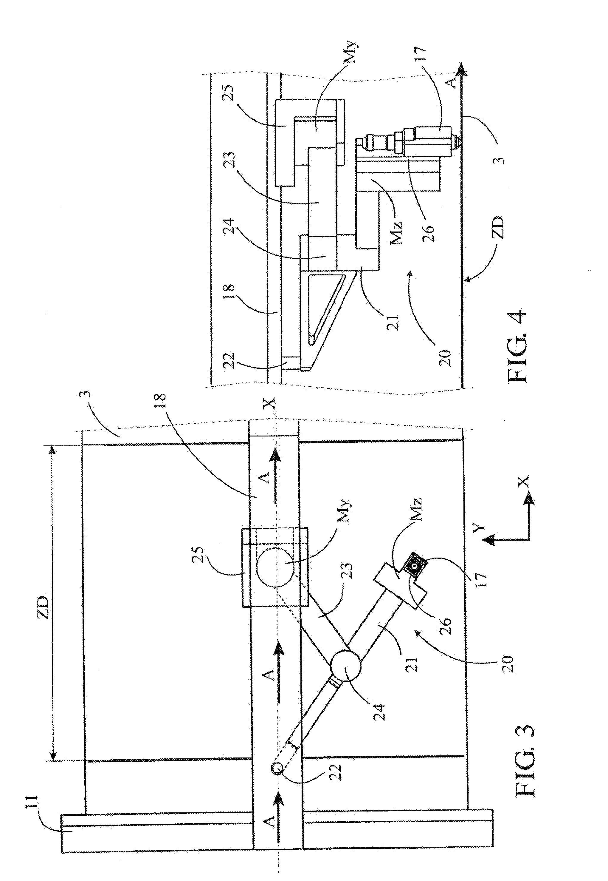
[0013]In a first embodiment, the mobile support comprises a variable-geometry mechanism. This variable-geometry mechanism can comprise on the one hand a rigid arm that supports at a first end said cutting head and at a second end a free pivot that slides in said longitudinal beam, and on the other hand a motorized arm having a length equal to half the length of said rigid arm and whereof a first end is coupled to a central point of said rigid arm by means of a joint and a second end is coupled to said second actuator, said second end of the motorized arm being integral with an horizontal carriage translatably mounted on said longitudinal beam and coupled to said first actuator.

second embodiment

[0014]In a second embodiment, the mobile support comprises a stationary-geometry mechanism. This stationary-geometry mechanism can comprise a first sliding carriage mounted in the longitudinal beam and coupled to the first actuator to move the cutting head along the longitudinal axis, and a transversal beam perpendicular to the longitudinal beam, fastened on said first carriage and supporting a second sliding carriage coupled to the second actuator to move the cutting head along the transversal axis.

[0015]The longitudinal beam advantageously extends parallel above said cutting zone, on at least the whole length of said cutting zone, and coincides with the longitudinal median axis of said cutting zone. Likewise, the mobile support has advantageously such a span that the cutting head covers at least the whole width of the cutting zone. In this case, said transversal beam has advantageously a length that exceeds the width of said cutting zone.

[0016]The cutting head can be integral with...


PUM

PropertyMeasurementUnit
Lengthaaaaaaaaaa
Speedaaaaaaaaaa
Widthaaaaaaaaaa

Abstract

A machine for flatbed cutting of pieces from a strip of material (3) wound in a coil and moving continuously. The cutting zone (ZD) comprises a cutting head (17) supported by a mobile support (20) translatably mounted on a stationary longitudinal beam (18) disposed parallel to the direction of movement (A) of the strip of material. It is coupled to a first actuator (Mx) for moving the cutting head (17) linearly along a longitudinal axis (X) parallel to the beam and comprises a variable-geometry mechanism (21-24) coupled to a second actuator (My) for moving the cutting head (17) linearly along a transverse axis (Y), perpendicular to the longitudinal axis (X). A central control unit (9) controls the actuators to move the cutting head (17) in the cutting zone (ZD) along a path determined by the contour of the pieces (2) to be cut and the speed of the material (3).

Description

TECHNICAL SCOPE[0001]This invention relates to a method for cutting pieces from a strip of material wound in a coil wherein one unwinds continuously said strip of material to move it in a same direction of movement at a predetermined speed, one cuts said pieces as said strip of material moves continuously using a cutting head that is moved linearly in an orthonormal plane parallel to said strip of material, along a transversal axis and along a longitudinal axis that corresponds to the direction of movement of said strip of material, both linear movements being combined to move said cutting head along any path contained in said orthonormal plane, and one evacuates said parts after cutting.[0002]This invention also relates to a cutting machine carrying out said method and comprising a frame provided with a cutting zone arranged to receive said strip of material, a cutting head supported by a mobile support arranged to move said cutting head linearly in an orthonormal plane parallel to...

Claims


Application Information

Patent Timeline
IPC IPC(8): B23K26/08B23K26/38
CPCB23K26/0846B23K26/0876B23K26/38
Inventor AUBRY, MARC
Owner DIMECO S AS
Why Eureka
Try Eureka