Assembly for a vehicle

a technology for vehicles and cameras, applied in closed circuit television systems, color television details, television systems, etc., can solve problems such as prone to malfunction, high cost, and complex structure of known camera assemblies, and achieve the effect of increasing the functionality of the protective lid and reducing the cost of the assembly

Active Publication Date: 2015-12-17
HUF HULSBECK & FURST GMBH & CO KG
View PDF2 Cites 22 Cited by
  • Summary
  • Abstract
  • Description
  • Claims
  • Application Information

AI Technical Summary

Benefits of technology

[0021]A particularly space-saving drive for the camera device, occupying a limited amount of structural space, can be implemented in that the drive unit drives a worm screw extending in the direction of movement for the camera unit, which is connected in an articulated manner, as well as movably coupled, to a first end of a lever element, wherein the second end of the lever element is connected in an articulated manner to the camera unit. The articulated connection enables a pivoting of the camera unit thereby, in particular when the camera unit is disposed in its active position, with its lens tilted in relation to the direction of movement.
[0022]In order to return and retain the push rod in its home position, from which it does not force the protective lid into the open position, a mechanically simple possibility is defined in the design of the invention, in that the push rod can be moved against the force of a spring element toward the carrier housing.
[0023]According to a further design of the assembly according to the invention, the protective lid has a printed circuit board, which has a light source for lighting the surrounding area when the protective lid is open and / or for lighting a vehicle make emblem attached to the outside of the protective lid. The printed circuit board can make it possible to light the exterior of the vehicle in the dark, or it can provide a backlighting for the vehicle make emblem, for which purpose, in addition to the vehicle make emblem and the printed circuit board having the light source, a light distribution device may also be provided on the handle designed in the shape of a cover.
[0024]It is provided in the design of the invention that an electrically conductive spring element is disposed between the protective lid and the carrier housing, which electrically connects the printed circuit board to a vehicle-side conductive element, and which applies a return force, forcing the protective lid into the closed position. As a result of the spring element, a drive element for returning the protective lid to its closed position is not necessary, such that the costs for the assembly can be reduced on the whole. The electrically conductive spring element serves to transfer power for supplying current and / or for transmitting data between the vehicle and the printed circuit board. As a result, it is possible to increase the functionality of the protective lid and the assembly on the whole, because the protective lid can then exhibit a lighting possibility or a sensor for detecting the approach of a user, for example. The vehicle-side conductive element can, for example, be a plug, in the simplest form, which is plugged into a socket formed on the housing, such that the vehicle-side plug is then connected to the printed circuit board via the electrically conductive spring element.

Problems solved by technology

The rearview mirrors only provide the vehicle driver with an insufficient range of observation because the rearview mirrors do not enable vision of the so-called blind spot.
This type of known camera assembly is structurally very complex, and thus, due to the complex displacement and pivotal mechanisms, is prone to malfunction.
Furthermore, the known assembly no longer fulfills the increasing demands for comfort from the customer in the world of today, and furthermore, exhibits only limited functionality of a view of the rearward space behind the vehicle visualized by the driver when backing into a parking space.
The camera moving together therewith in this manner increases, in a disadvantageous manner, the mass of the protective element, for which reason greater torques are necessary for executing its hinged motion.

Method used


Image

  • Assembly for a vehicle
  • Assembly for a vehicle
  • Assembly for a vehicle

Examples


Embodiment Construction

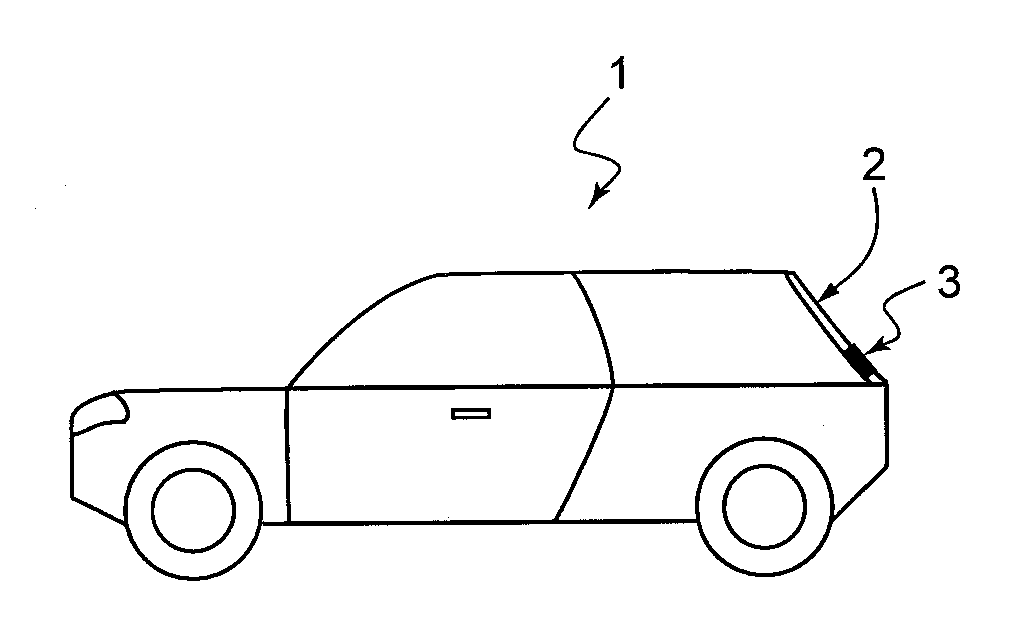
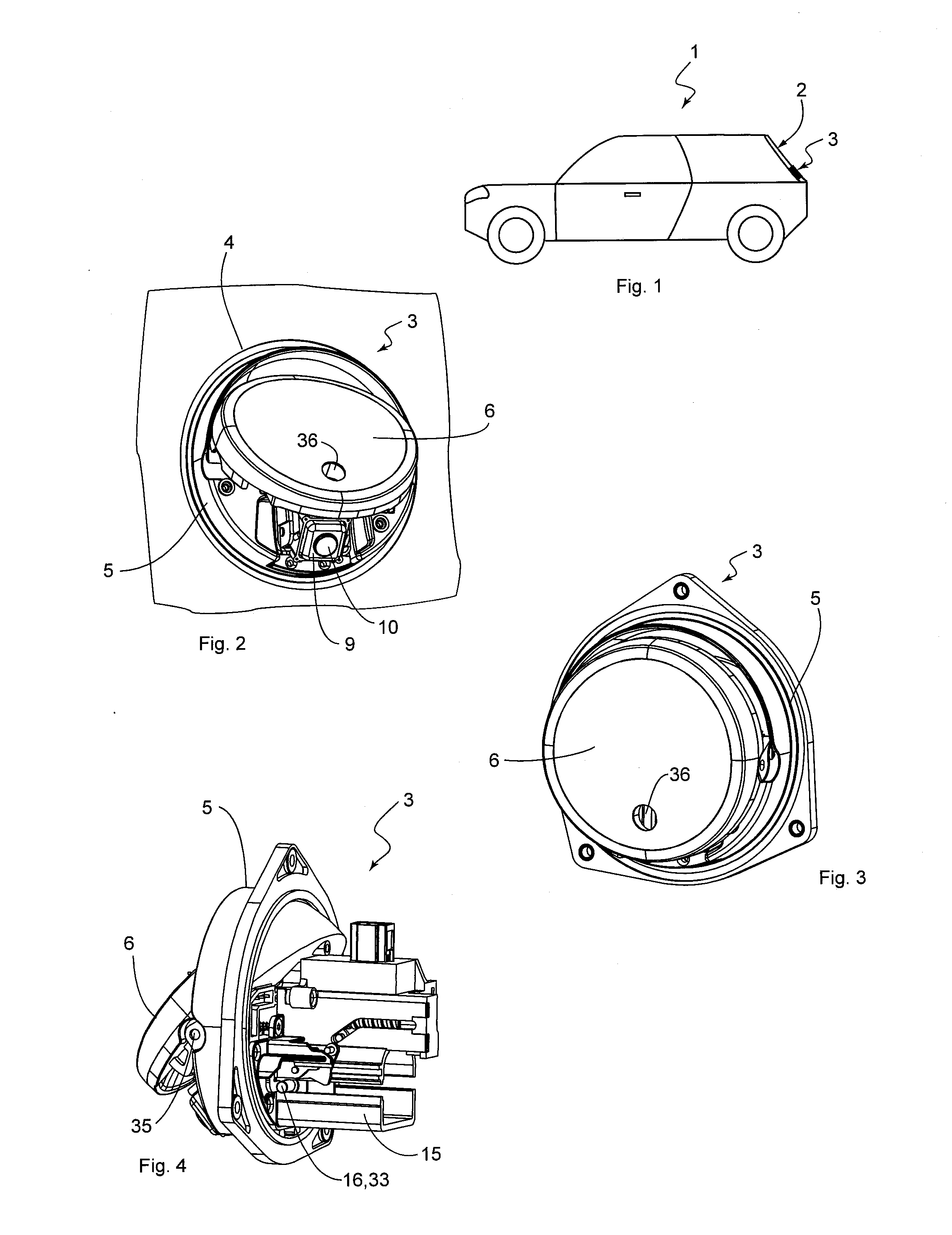
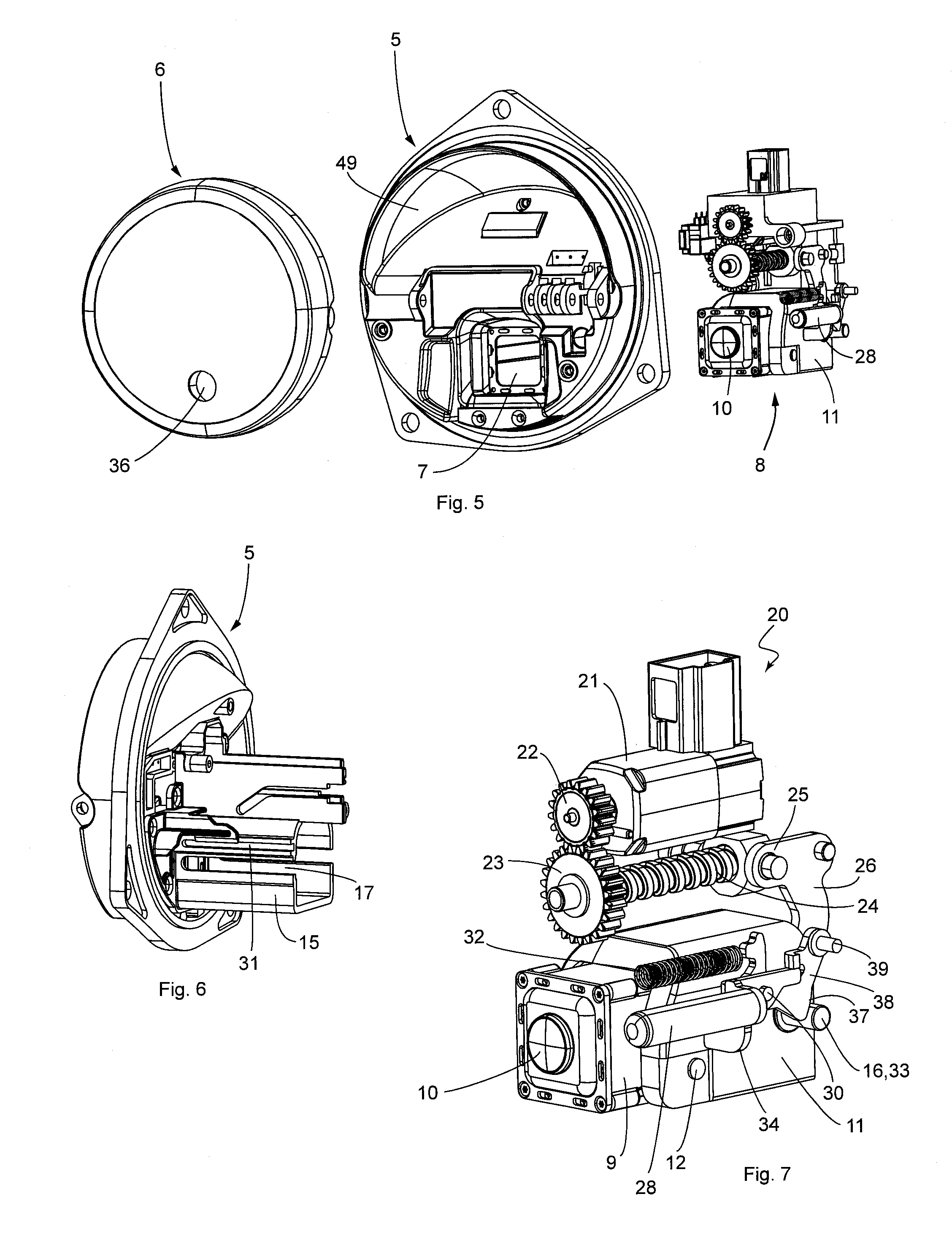
[0055]A vehicle 1 in the form of a passenger car is depicted by way of example in FIG. 1, which, in the example, has a lid, or hatchback 2, respectively, on which an assembly 3 according to the invention is attached. The assembly 3 is disposed in an opening 4 in the exterior paneling of the vehicle 1, and attached there, as is shown in particular in FIG. 2. The assembly 3 is depicted in a front view in FIG. 3 and in a side view in FIG. 4. The assembly 3 comprises a carrier housing 5, having a cylindrical, or shell-like shape, respectively. A protective lid 6 is movably supported on the carrier housing 5, between a closed position (see FIG. 3) and an open position (see FIGS. 2 and 4). In the closed position, the protective lid 6 closes a through-hole 7, which can be seen more clearly in FIG. 5, that extends from the front surface of the carrier housing 5, through the carrier housing 5, to the back surface, which is shown in FIG. 8. When the protective lid 6 is in its open position, h...


PUM


Abstract

A solution that offers increased comfort for the user and increases the value of the vehicle is obtained with an assembly for a vehicle, having a carrier housing, which has a through-hole, a drive unit, which is attached to the carrier housing, a camera unit, which can move between a standby position and an active position and a protective lid, which can move between an open position and a closed position. An actuating element is movably coupled to the drive unit and forces the protective lid into its open position when the vehicle is driven in reverse and the camera unit is in the active position. The camera unit assumes a collision monitoring position when the vehicle is being driven forwards, in which position the protective lid is disposed in its closed position, and in which the camera unit is disposed at a monitoring opening formed in the protective lid, for filming the following or preceding traffic.

Description

BACKGROUND[0001]The invention relates to an assembly, in particular a camera assembly, for a motor vehicle, wherein the assembly comprises a carrier housing, which is disposed in an opening in an exterior paneling of the vehicle, and which has a through-hole, a drive unit, which is attached to the back surface of the carrier housing, a movably supported camera unit, which can be moved by means of the drive unit between at least a standby position and an active position, in which at least the lens of the camera unit protrudes out of the through-hole in the carrier housing and which is oriented at a slant to the movement direction of the camera unit, a protective lid movably supported on the carrier housing, which can move between a closed position, in which it closes the through-hole in the carrier housing, and in which the camera is disposed, seen from the outside, behind the protective lid, and an open position, in which it opens the through-hole in the carrier housing, wherein an ...

Claims


Application Information

Patent Timeline
Patent Type & Authority Applications(United States)
IPC IPC(8): B60R11/04
CPCB60R2001/1253B60R11/04
Inventor BARTHEL, JOACHIMWIETKAMP, STEPHAN
Owner HUF HULSBECK & FURST GMBH & CO KG
Why Eureka
Try Eureka