Rugged Lighting System

a lighting system and arugula technology, applied in the field of rugged lighting systems, can solve the problems of not being able to unbundle lighting products, led lighting systems and their internal electronic components are susceptible to impact and moisture, and many products are not sufficiently constructed to withstand extremes, etc., to achieve the effect of ruggedness, energy and thermal efficiency, versatility, and unbundling of key components

Active Publication Date: 2015-12-17
INDUSTRALIGHT
View PDF13 Cites 9 Cited by
  • Summary
  • Abstract
  • Description
  • Claims
  • Application Information

AI Technical Summary

Benefits of technology

[0003]In accordance with the above, a new and innovative, rugged lighting system is provided. The problem of achieving a lighting s

Problems solved by technology

Despite the adoption of this technology, a number of technological deficiencies exist in current LED lighting products for mining and large industrial applications.
For example, many products are not sufficiently constructed to withstand the extreme and varied environments encountered.
Thus, LED lighting systems and their internal electronic componentry are susceptible t

Method used


Image

  • Rugged Lighting System
  • Rugged Lighting System
  • Rugged Lighting System

Examples


Embodiment Construction

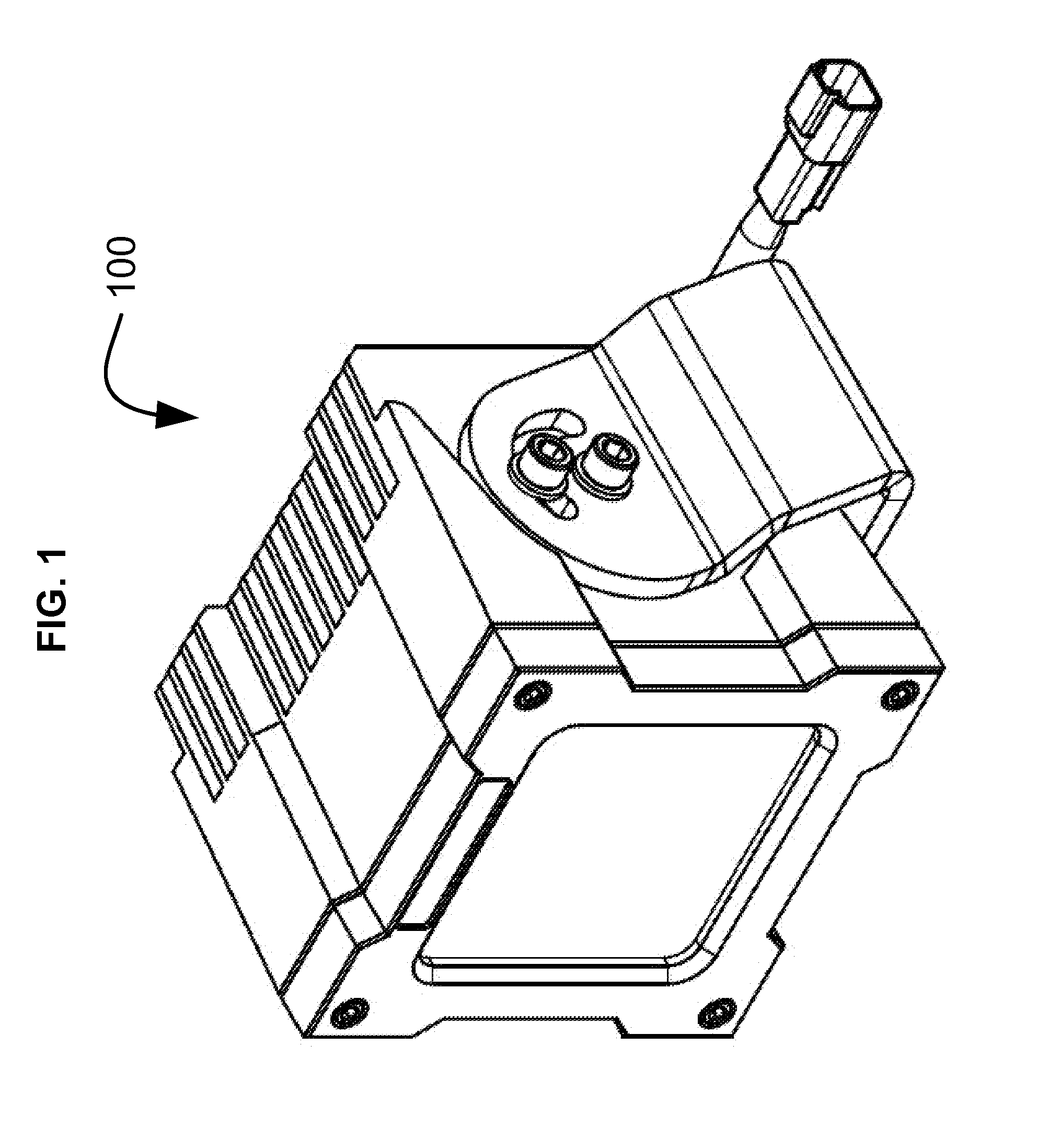
[0032]The present invention in its various embodiments, some of which are depicted in the figures herein, is a rugged lighting system. FIG. 1 depicts the outside of one embodiment of a fully assembled, rugged lighting system 100.

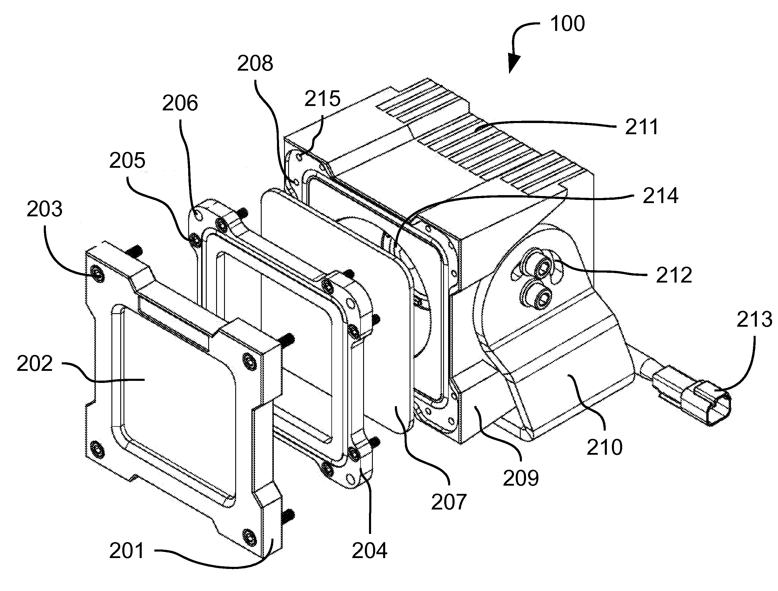
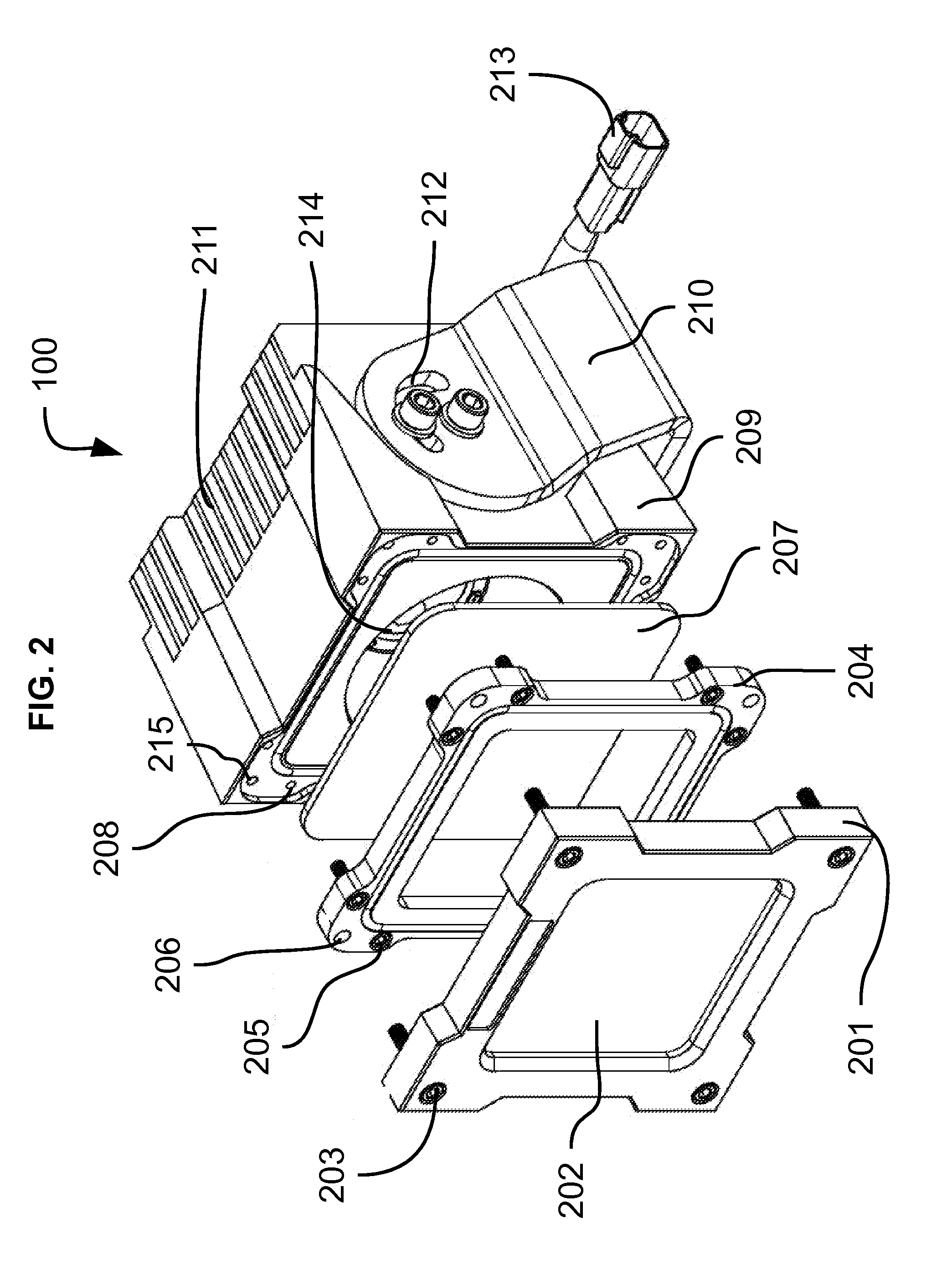
[0033]Referring now to FIG. 2, an exploded perspective view of a rugged lighting system 100 with various components is shown. In preferred embodiments, the system 100 is comprised of a first lens 207, second lens 202, and housing unit 209 with LED array 214.

[0034]The first lens 207 is removeably attachable to the front of the housing unit 209.

[0035]In certain embodiments, the means for removable attachment of the first lens 207 is a first lens bezel 204 configured to overlap a portion of the perimeter of the first lens 207. Depending on the embodiment, the first lens bezel 204 may be either permanently affixed to or separable from the first lens 207. In the illustrated embodiment, this first lens bezel 204 is separable and shaped as a key to precisely fit th...


PUM


Abstract

A new and innovative, rugged lighting system is provided. The problem of achieving a lighting system that optimizes ruggedness, luminosity, energy and thermal efficiency, versatility, and unbundling of key components is solved. Embodiments of the present invention include a rugged lighting system comprising a housing unit with a body with integrally formed back, sides, and a front with an opening to provide access to the interior of the housing unit; a first lens configured to substantially cover the opening; a first lens bezel configured to removeably attach to the housing unit over the first lens; a second lens configured for placement over the first lens; and a second lens bezel configured to removeably attach to the housing unit over the first lens bezel. Various embodiments further include a light module within the housing unit with a light emitting diode (LED) mounted to an electronics module having a printed circuit board for operating the LED.

Description

CROSS-REFERENCE TO RELATED APPLICATIONS[0001]This application claims priority to U.S. Provisional Application No. 62 / 006,076, filed on May 31, 2014.BACKGROUND OF THE INVENTION[0002]Many industries require vehicles to operate continually, day and night, in harsh conditions. The mining industry is one such example. Operators are often required to work in dark and / or nighttime conditions on heavy vehicles. Lighting in these circumstances is paramount. Today, traditional lighting technology is being surpassed by LED lighting because of the latter's energy and thermal efficiency, not to mention increased brightness. Despite the adoption of this technology, a number of technological deficiencies exist in current LED lighting products for mining and large industrial applications. For example, many products are not sufficiently constructed to withstand the extreme and varied environments encountered. Thus, LED lighting systems and their internal electronic componentry are susceptible to imp...

Claims


Application Information

Patent Timeline
IPC IPC(8): F21V15/01F21V5/00F21V23/04F21V17/00F21V31/00F21V25/10F21V5/04F21V17/12
CPCF21V15/01F21V5/048F21V5/008F21V17/12F21Y2101/02F21V31/005F21V25/10F21V23/0464F21V17/002F21W2131/40F21Y2115/10B60Q1/0483F21S41/143F21S41/29F21S41/28F21S41/50F21S45/50F21S45/48B60Q1/245
Inventor THOMSEN, J. RYANMARKS, SETH M.WILLIAMS, MARKSHUMWAY, JIMWOOLINGTON, CHRISTOPHER
Owner INDUSTRALIGHT
Why Eureka
Try Eureka