Lens Moving Device, Camera Module and Optical Apparatus

Active Publication Date: 2015-12-17
LG INNOTEK CO LTD
View PDF5 Cites 30 Cited by
  • Summary
  • Abstract
  • Description
  • Claims
  • Application Information

AI Technical Summary

Benefits of technology

[0036]According to an exemplary embodiment of the present disclosure, a location of the bobbin during auto-focusing and handshake compensation operations may be accurately detected, because the location of the sensing magnet may be detected by the location detection sensor such as Hall sensor, by installing the sensing magnet on an outer side surface of the bobbin.
[

Problems solved by technology

However, there is still a risk of performance degradation such as disequilibration

Method used


Image

  • Lens Moving Device, Camera Module and Optical Apparatus
  • Lens Moving Device, Camera Module and Optical Apparatus
  • Lens Moving Device, Camera Module and Optical Apparatus

Examples


Embodiment Construction

[0043]Hereinafter, an exemplary embodiment of the present disclosure will be described with reference to the enclosed drawings.

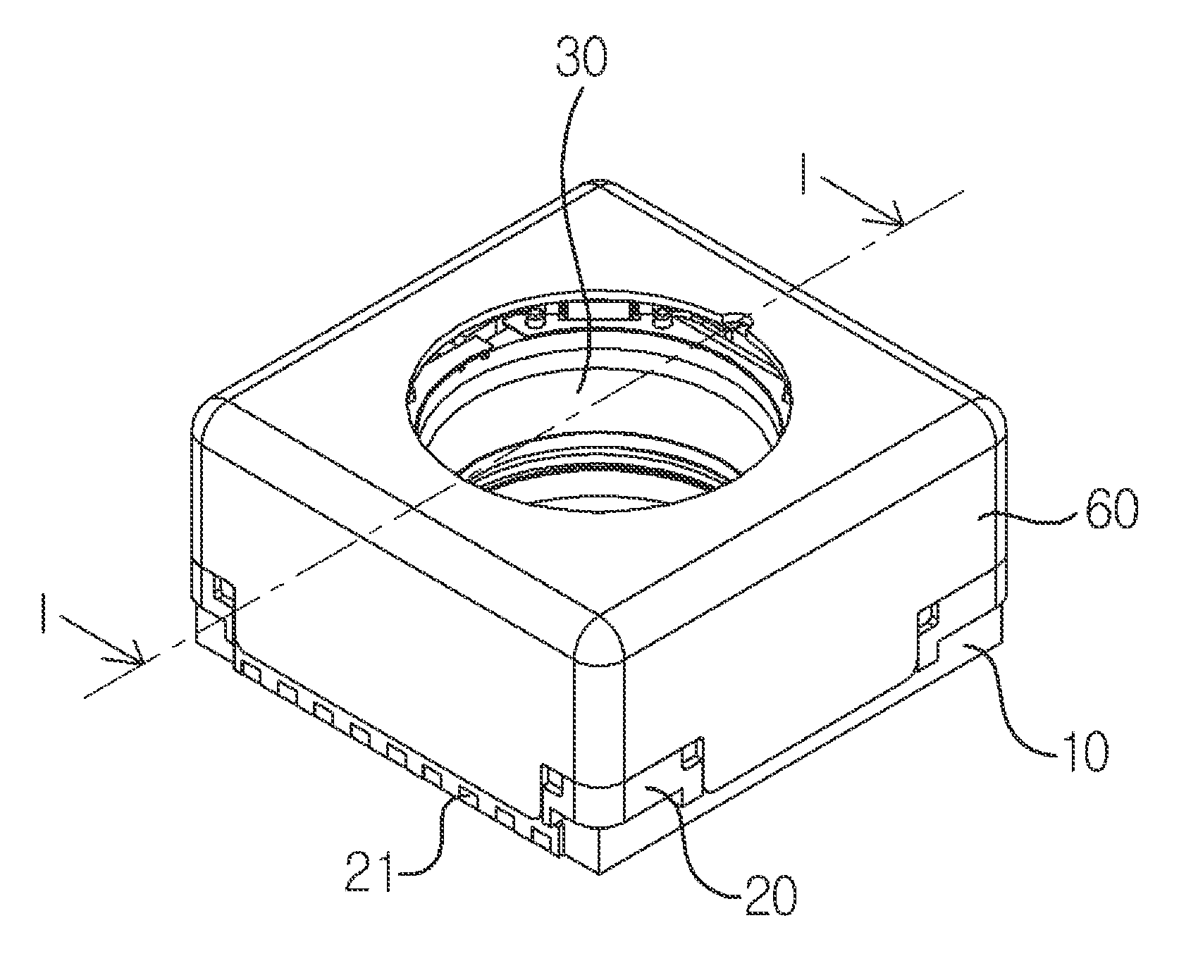
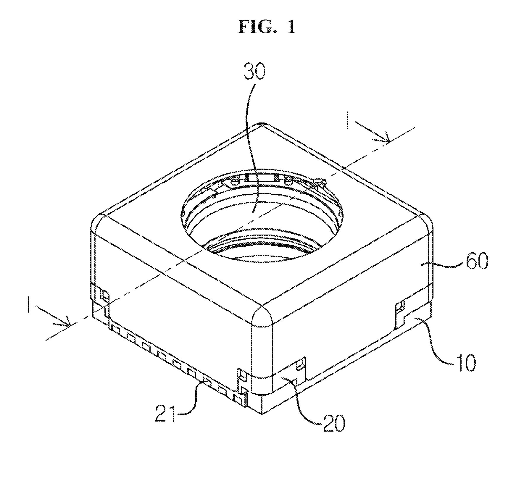
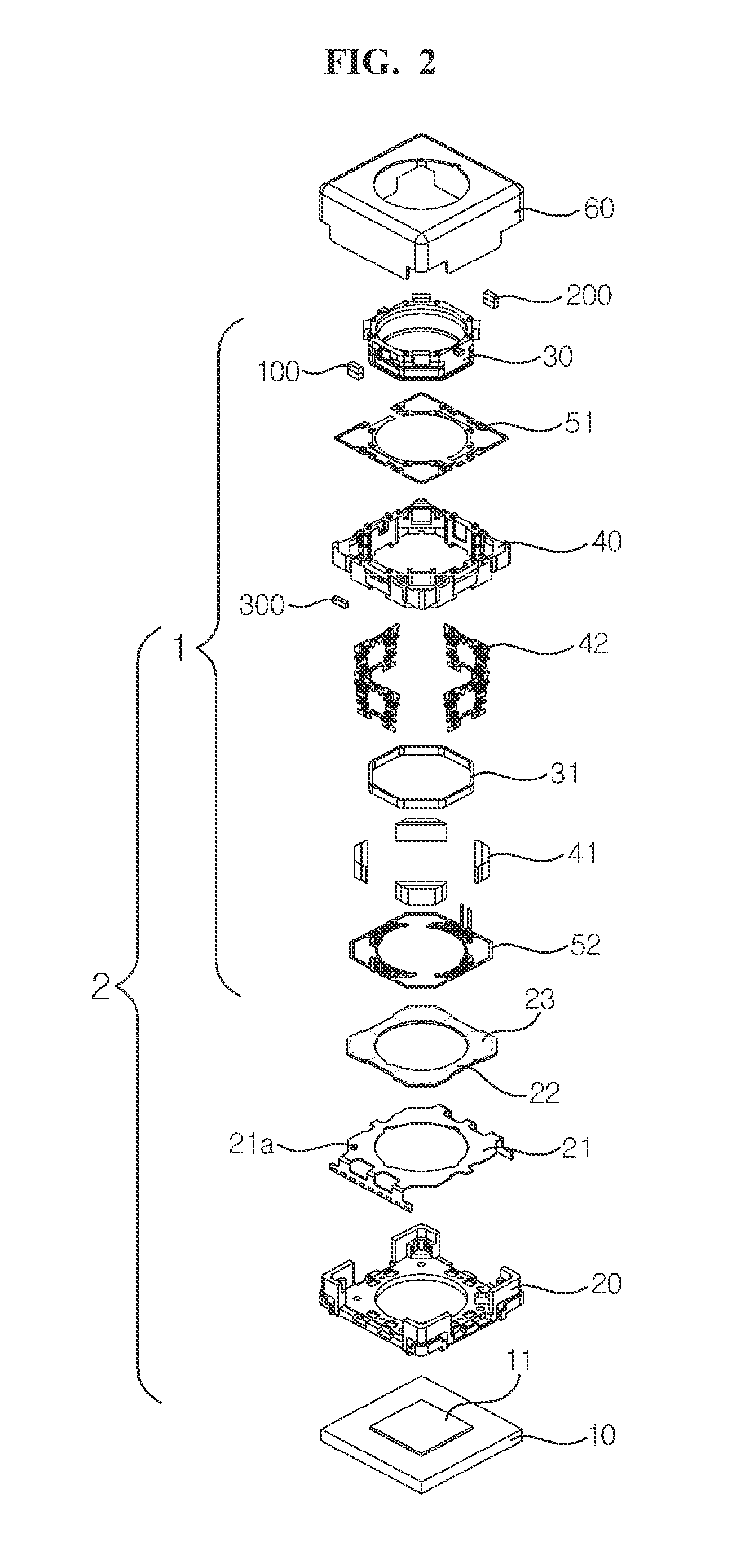
[0044]FIG. 1 is a schematic perspective view illustrating a camera module according to an exemplary embodiment of the present disclosure; FIG. 2 is an exploded perspective view of FIG. 1; FIG. 3 is an enlarged perspective view illustrating a bobbin of FIG. 2; FIG. 4 is an enlarged perspective view illustrating a holder member of FIG. 2; and FIG. 5 is an I-I sectional view of FIG. 1.

[0045]As illustrated in FIGS. 1 and 2, a lens moving device according to an exemplary embodiment of the present disclosure may include a first lens driving unit (1) and a second lens driving unit (2). Here, the first lens driving unit (1) is a lens driving unit for auto-focusing function, and the second lens driving unit (2) is a lens driving unit for handshake compensation function.

[0046]Meanwhile, hereinafter, a first driving unit (31) may also refer to as a first coil (31), whi...


PUM


Abstract

A lens moving device is provided. The lens moving device includes: a bobbin; a first driving unit coupled to the bobbin; a second driving unit configured to move the first driving unit through an electromagnetic interaction with the first driving unit; a sensing magnet disposed on one side of the bobbin; a location detection sensor configured to sense a location of the sensing magnet; and a correction magnet disposed on an opposite side of the bobbin.
According to the present disclosure, static tilt and dynamic tilt of the bobbin, to which a lens module is to be coupled, may be enhanced by a sensing magnet and a correction magnet which establish magnetic force equilibrium with each other.

Description

CROSS-REFERENCE TO RELATED APPLICATION[0001]This application claims the benefit under 35 U.S.C. §119 of Korean Application No. 10-2014-0070525, filed Jun. 11, 2014, which is hereby incorporated by reference in its entirety.BACKGROUND OF THE DISCLOSURE[0002]1. Field of the Invention[0003]The present disclosure relates to a lens moving device, a camera module, and an optical apparatus.[0004]2. Background of the Related Art[0005]A camera module may include an image sensor, a printed circuit board configured to deliver electric signals to the image installed on the printed circuit board, an infrared cut-off filter configured to block light in infrared area from incident into the image sensor, and an optical system including at least one lens configured to deliver an image to the image sensor. Here, a lens moving device configured to perform auto-focusing function and handshake compensation function may be installed in the optical system.[0006]The lens moving device may be formed in a va...

Claims


Application Information

Patent Timeline
IPC IPC(8): G02B7/09
CPCG02B7/09G02B7/08G02B27/646G03B5/04G03B17/12G03B2205/0069H04N23/54G03B3/10G03B13/36H04N23/55H02K41/0356H02K11/215G03B2205/0023
Inventor HAN, JIN SUKYEO, IN JAECHO, JAE HONG
Owner LG INNOTEK CO LTD
Why Eureka
Try Eureka