Terminal connection strip, method of manufacturing crimp terminal, wire crimping device, and method of crimping wire

Active Publication Date: 2015-12-17
FURUKAWA ELECTRIC CO LTD +1
View PDF13 Cites 11 Cited by
  • Summary
  • Abstract
  • Description
  • Claims
  • Application Information

AI Technical Summary

Benefits of technology

[0035]The present invention can provide a terminal connection strip and a method of manufacturing a crimp terminal by which a crimp terminal provided with a hollow crimping section having high quality and excellent water-blocking performance and excellent c

Problems solved by technology

Such connectors are used under various environments and hence, there may be a case where unintended moisture adheres to a surface of the insulated wire due to condensation brought about by a change in ambient temperature or the like.
There is a drawback that, when moisture intrudes into the inside of the connector along the surface of the insulated wire, a surface of a wire conductor exposed from a distal end of the insulated wire corrodes.
Accordingly, the manufacturing efficiency of a closed-barrel-type crimp terminal provided with a hollow crimping section is remarkably low.
However, in inserting the conductor tip into the inside of the crimping section, the conductor tip and the slide cutter (5) which i

Method used


Image

  • Terminal connection strip, method of manufacturing crimp terminal, wire crimping device, and method of crimping wire
  • Terminal connection strip, method of manufacturing crimp terminal, wire crimping device, and method of crimping wire
  • Terminal connection strip, method of manufacturing crimp terminal, wire crimping device, and method of crimping wire

Examples


Example

First Embodiment

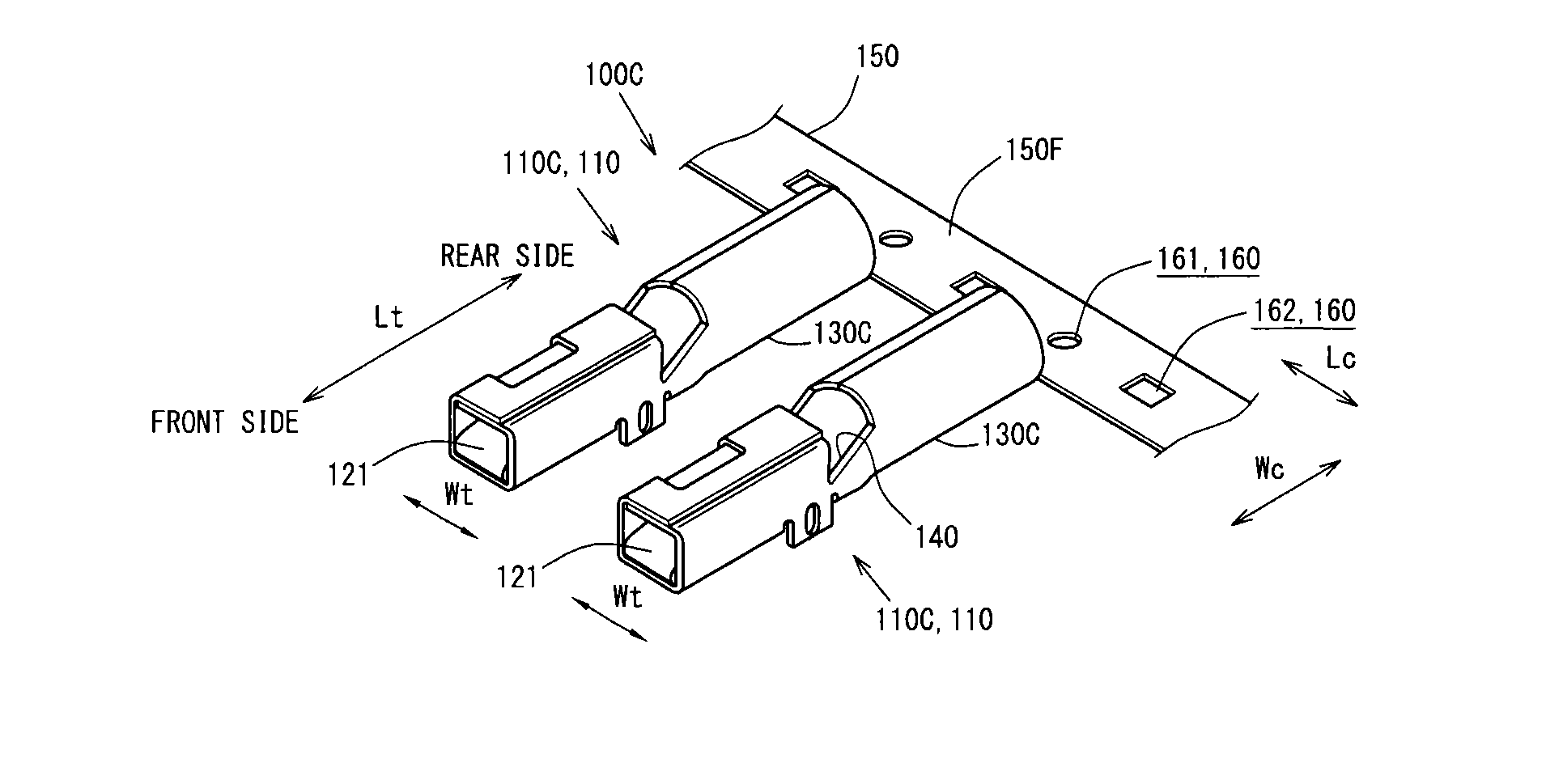
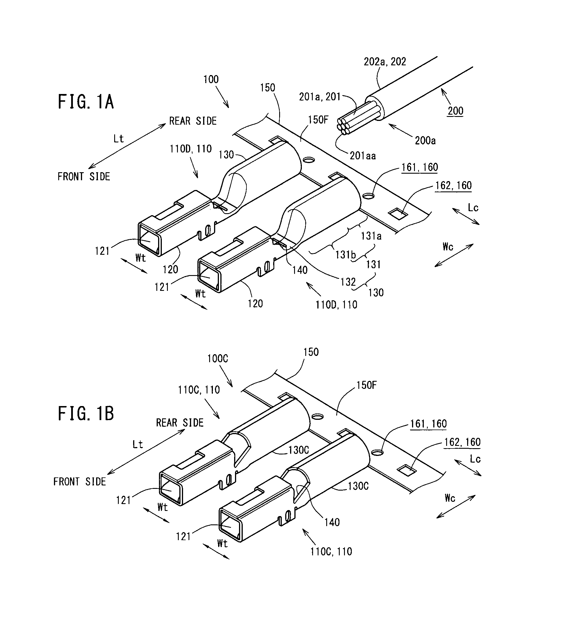
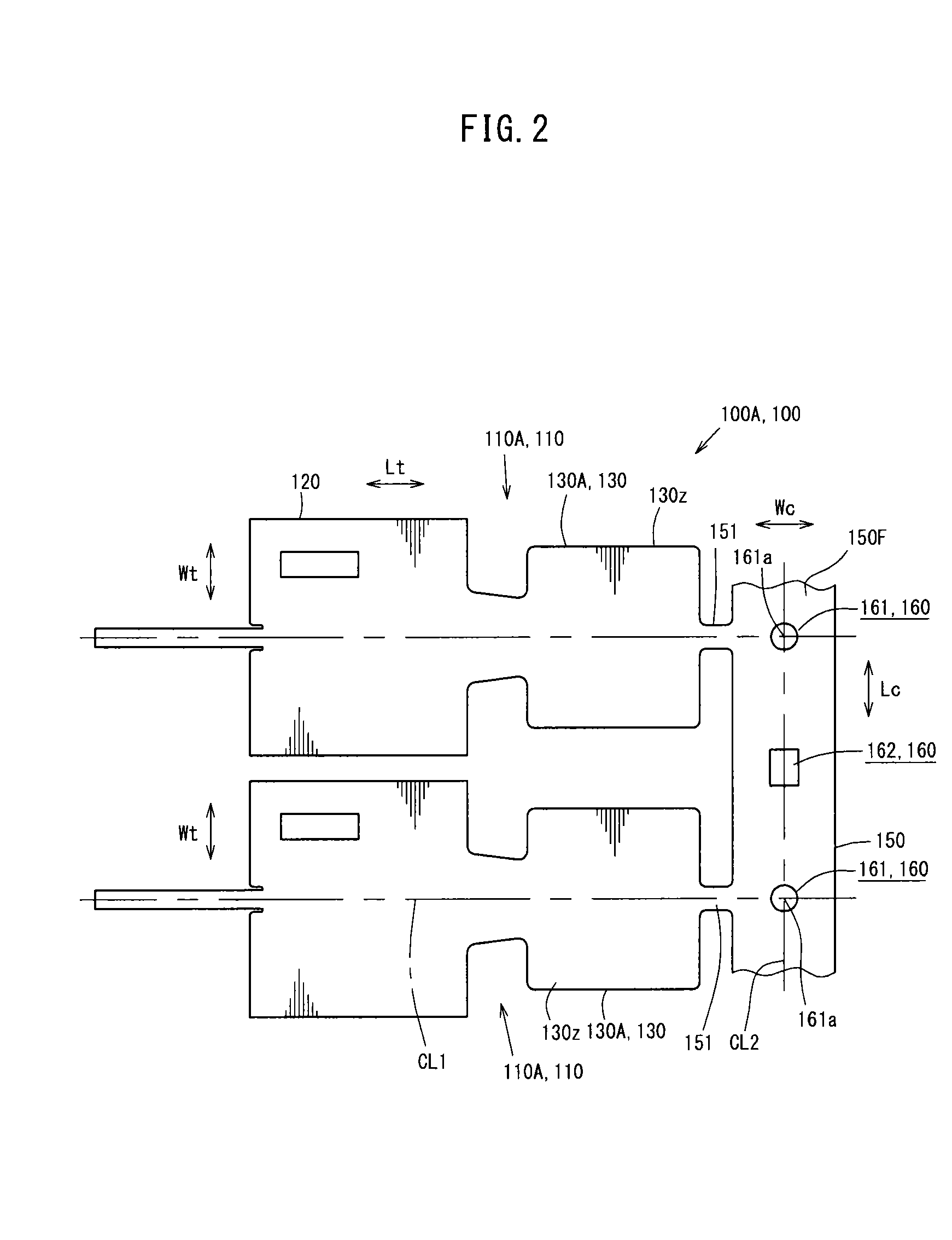
[0060]FIG. 1A is a perspective view of a terminal connection strip 100 according to this embodiment. This will be described in more detail. FIG. 1A shows a state immediately before a wire tip 200a is inserted into a crimping section 130 of a female crimp terminal 110. FIG. 1B is a perspective view showing a state immediately after a welding step, and is a perspective view of a terminal connection strip 100C before a sealing portion forming step.

[0061]In this embodiment, as shown in FIG. 1A, the terminal connection strip 100C is formed of an integral body constituted of a carrier 150 formed into a strip shape, and a plurality of female terminal fittings 110D which project from at least one edge side of the carrier 150 in a carrier width direction Wc.

[0062]The terminal fitting 110D can be separated from the carrier 150 as a closed-barrel-type female crimp terminal 110 by cutting a connection portion 151 that connects the carrier 150. Further, a wire provided with a cri...

Example

Second Embodiment

[0220]Another embodiment is described.

[0221]The same symbols are applied to the constitution similar to the constitution of the above-mentioned first embodiment and the explanation of the constitution is omitted.

[0222]FIG. 15 is a front view showing the overall structure of a wire crimping device 400, FIG. 16 is a right side view showing the overall structure of the wire crimping device 400 partially described in a cross section, and FIG. 17A to FIG. 17C are constitutional explanatory views of an anvil jig 421 and a crimper jig 451. This will be described in more detail. FIG. 17A is a front view of a wire crimping area Pa of the wire crimping device 400 and an area around the wire crimping area Pa before carrier cutting, and FIG. 17B is a longitudinal cross-sectional view of the wire crimping area Pa of the wire crimping device 400 and the area around the wire crimping area Pa before carrier cutting.

[0223]FIG. 17C is an enlarged view of part “X” in FIG. 17B. FIG. 18...


PUM

PropertyMeasurementUnit
Thicknessaaaaaaaaaa
Lengthaaaaaaaaaa
Widthaaaaaaaaaa

Abstract

The terminal connection strip includes: a carrier formed in a strip shape; and a plurality of terminal fitting which project from at least one edge side of the carrier in a width direction. The terminal fitting includes a crimping section which connects by crimping at least a conductor tip of an insulated wire provided with the conductor tip where a conductor is covered with an insulating cover and the conductor is exposed by peeling off the insulating cover on a distal end side of the insulated wire to the terminal fitting. The crimping section is formed into a hollow shape which allows the insertion of at least the conductor tip from a proximal end side of the crimping section and allows the crimping section to surround the conductor tip.

Description

TECHNICAL FIELD[0001]The present invention relates to a terminal connection strip which is used in manufacturing a crimp terminal mounted on a connector of an automobile-use wire harness or the like, for example, and is constituted of a carrier formed in a strip shape and a plurality of terminal fittings projecting from at least one end side of the carrier in the width direction by way of press working of a base material. The present invention also relates to a method of manufacturing a crimp terminal which is manufactured using the terminal connection strip. The present invention also relates to a wire crimping device and a wire crimping method where a crimp terminal of a terminal connection strip which is constituted of a carrier formed in a strip shape and a plurality of crimp terminals projecting from at least one end side of the carrier in the width direction is connected by crimping to a conductor tip formed by exposing a conductor by peeling off an insulating cover on a dista...

Claims


Application Information

Patent Timeline
IPC IPC(8): H01R4/18H01R43/05H01R43/02
CPCH01R4/187H01R4/183H01R43/02Y10T29/53235Y10T29/49215Y10T29/4922H01R43/05H01R43/048H01R43/16H01R4/20H01R43/0221
Inventor TONOIKE, TAKASHIKAWAMURA, YUKIHIROYAGI, SABUROTAKAMURA, SATOSHIHYOTANI, TAKESHIKITAGAWA, KOICHIARAMAKI, EIJI
Owner FURUKAWA ELECTRIC CO LTD
Why Eureka
Try Eureka