Electrical cord plug eject mechanism

a technology of electric cord and ejector, which is applied in the direction of two-part coupling devices, electrical equipment, coupling parts engagement/disengagement, etc., can solve the problems of damage to the plug and outlet, insufficient disconnection of the cord by the user at the device location, and attempts to remotely control the disconnection of the plug from the outlet. , to achieve the effect of reducing pressur

Inactive Publication Date: 2015-12-17
BRAINWAVE RES CORP
View PDF26 Cites 6 Cited by
  • Summary
  • Abstract
  • Description
  • Claims
  • Application Information

AI Technical Summary

Benefits of technology

[0013]In a further alternative, the solenoid(s) may be replaced by cylinder and piston arrangement, the piston serving as the ejector rod. A pressurized reservoir may be coupled to the cylinder through a control valve. Upon activation of the control valve, the valve is opened to apply pressure from the reservoir to the cylinder to drive the piston to the ejected state. Upon successful plug ejection, a second control valve can be activated to reduce the pressure. A spring, positioned between the piston and the front of the plug housing, impels the piston to its retracted state. The control valves may function under control of a microprocessor in response to receipt of the manual trigger. A compressor may be included in the plug housing to replenish the pressure within the reservoir.

Problems solved by technology

A pull on the cord by the user at the device location may not be sufficient to effect disconnection or, worse, damage the plug and outlet.
Attempts to remotely control disconnection of a plug from an outlet have been prone to problems such as inadvertent disconnection, repetitive control pulsing that can damage or burn out the plug device, or lack of sufficient force to completely separate the plug from its receptacle.

Method used


Image

  • Electrical cord plug eject mechanism
  • Electrical cord plug eject mechanism
  • Electrical cord plug eject mechanism

Examples


Embodiment Construction

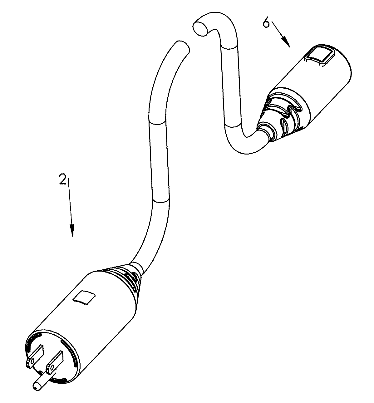
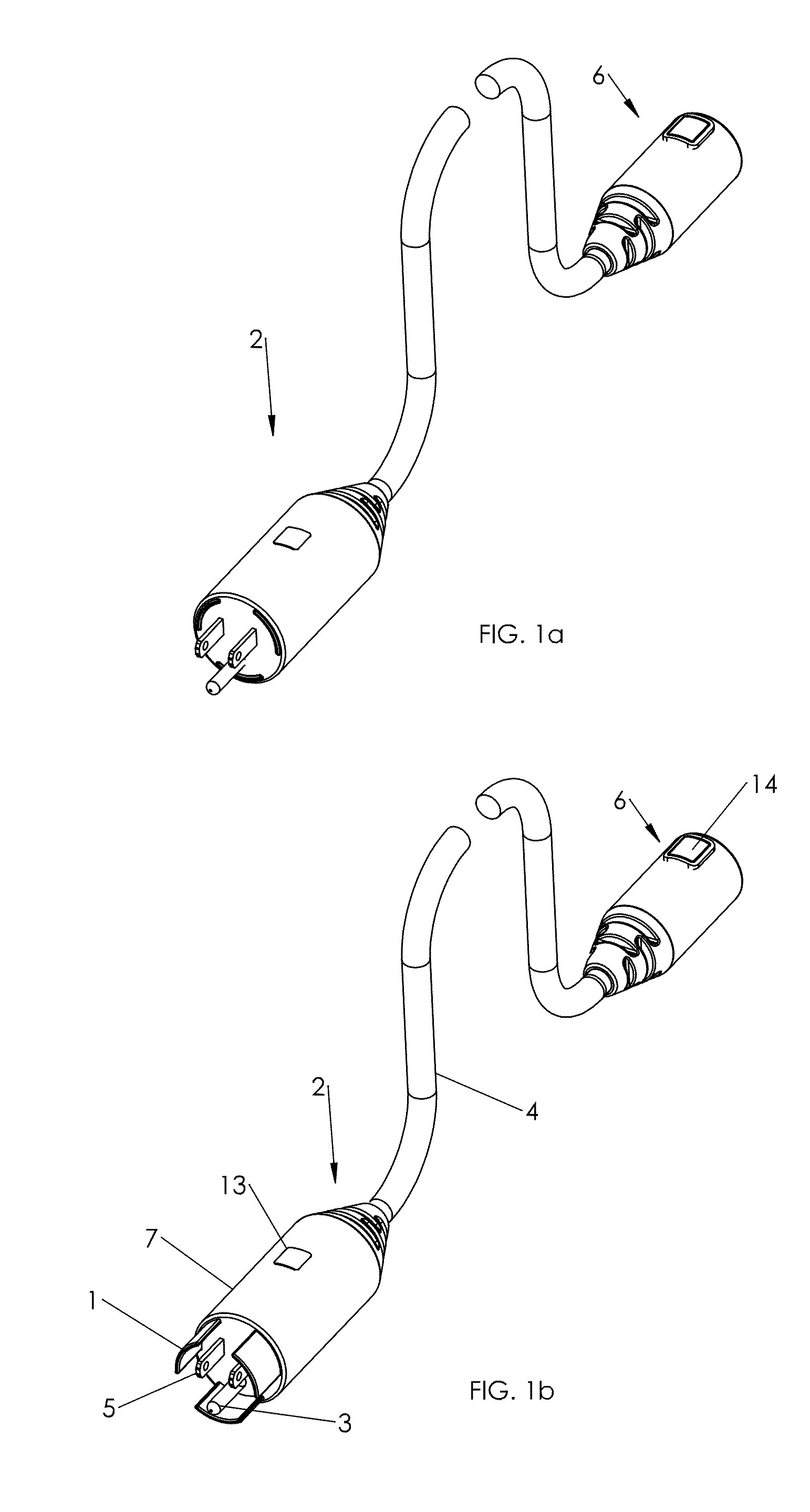
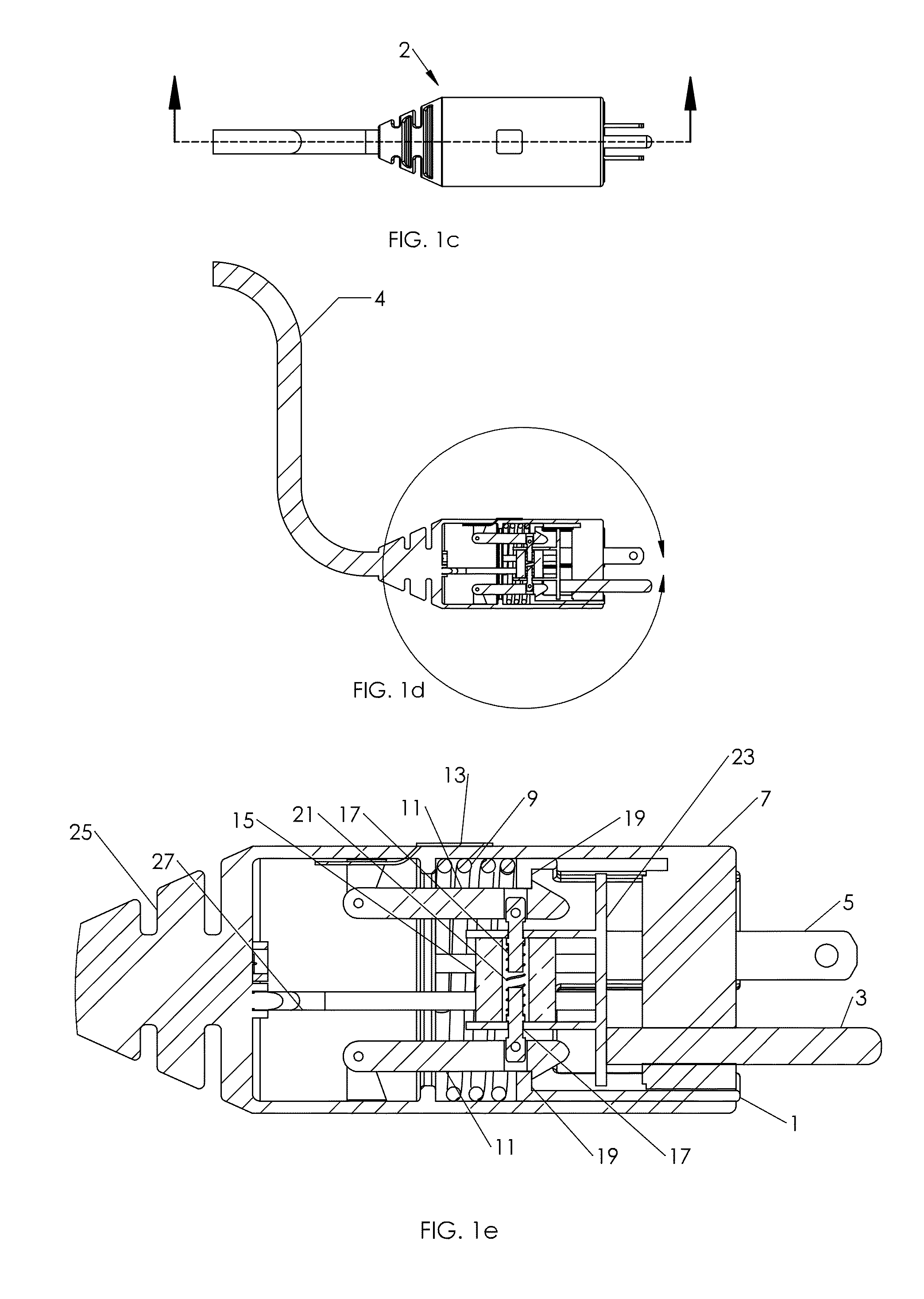
[0074]An electrical extension cord 2 having a cylindrical male plug 7 at one end and a female plug 6 is illustrated in FIGS. 1a and 1b. Conductive prongs 5 and ground prong 3 extend from plug 7. Shell 1, within plug 7, surrounds prongs 5. Shell 1 comprises sections formed in a cylindrical configuration with a surface area substantially corresponding in size to that of the circumference of the housing of plug 7. When shell 1 is retracted within plug 7, as shown in FIG. 1a, prongs 5 are able to mate with a female receptacle or plug to establish an electrical connection therewith. When shell 1 is extended from plug 7, as shown in FIG. 1b, a mated connection with plug 7 is precluded. Manual button 13 is tied to a switch component within plug 7. Manual button 14 is tied to a switch component within female plug 6. Components of plug 7 are shown in detail in FIG. 1e for the retracted position of shell 1 and in FIG. 1h for the extended position of shell 1. Depression of either button 13 or ...


PUM


Abstract

A plug housing includes an ejector mechanism and a controller electrically coupled to the ejector mechanism for detaching electrical conductive blades of the plug from a mated connection with a female connector. In response to a switch signal from the controller, a solenoid is activated to release a latch in the mechanism, thereby permitting the force of a compressed spring to impel a structure outwardly from the plug. The controller may be located remotely from the plug and superimpose control signals to the plug over the power lines within the cord.

Description

[0001]This is a continuation-in-part of application Ser. No. 14 / 587,881, filed Dec. 31, 2014 on behalf of inventors Jean-Guy Gagne, James Rogers and Patrick Belanger. The benefit of provisional application 61 / 923,318, filed Jan. 3, 2014 and provisional application 62 / 043,091, filed Aug. 28, 2014, is claimed under 35 U.S.C. 119(e).BACKGROUND[0002]This disclosure is related to electrical cord and plug devices and, more particularly, to a mechanism for remotely controlling ejection of a plug from an outlet or from another cord or device to which the plug is connected.[0003]A variety of electrical applications require a long electrical cord so that a user can operate an electrical appliance or other device at a relatively great distance from the power source. For example, vacuum cleaners are commonly provided with electrical cords that enable use over a large area, often extending to adjoining rooms. As another example, a long extension cord may be required for operation of a device at ...

Claims


Application Information

Patent Timeline
Patent Type & Authority Applications(United States)
IPC IPC(8): H01R13/633H01R13/6581H01R13/66H01R13/70
CPCH01R13/633H01R13/665H01R13/6581H01R13/70H01R13/635H01R13/7132H01R24/30H01R2103/00
Inventor GAGNE, JEAN-GUYROGERS, JAMES W.BELANGER, PATRICK
Owner BRAINWAVE RES CORP
Why Eureka
Try Eureka