Alternative energy generator

a technology of alternative energy and generators, applied in the direction of dynamo-electric machines, magnetic circuit rotating parts, magnetic circuit shapes/forms/construction, etc., can solve the problems of increasing the cost of windmills used to capture wind energy, solar panels, and providing a cost-ineffective source of energy, etc., to increase the torque, increase the torque, increase the effect of torqu

Active Publication Date: 2015-12-17
FARQUHARSON ASTON GUSTAVOUS
View PDF6 Cites 4 Cited by
  • Summary
  • Abstract
  • Description
  • Claims
  • Application Information

AI Technical Summary

Benefits of technology

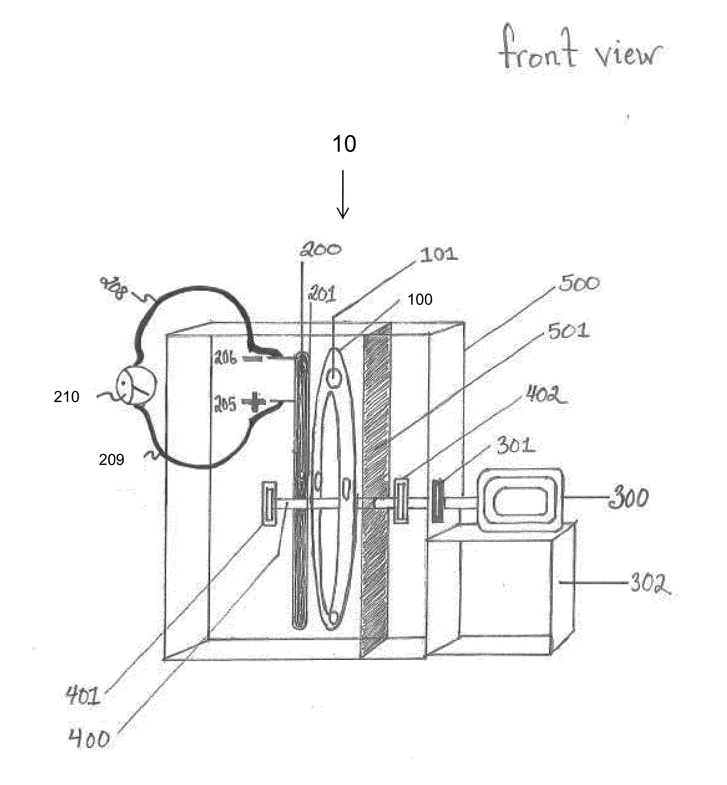
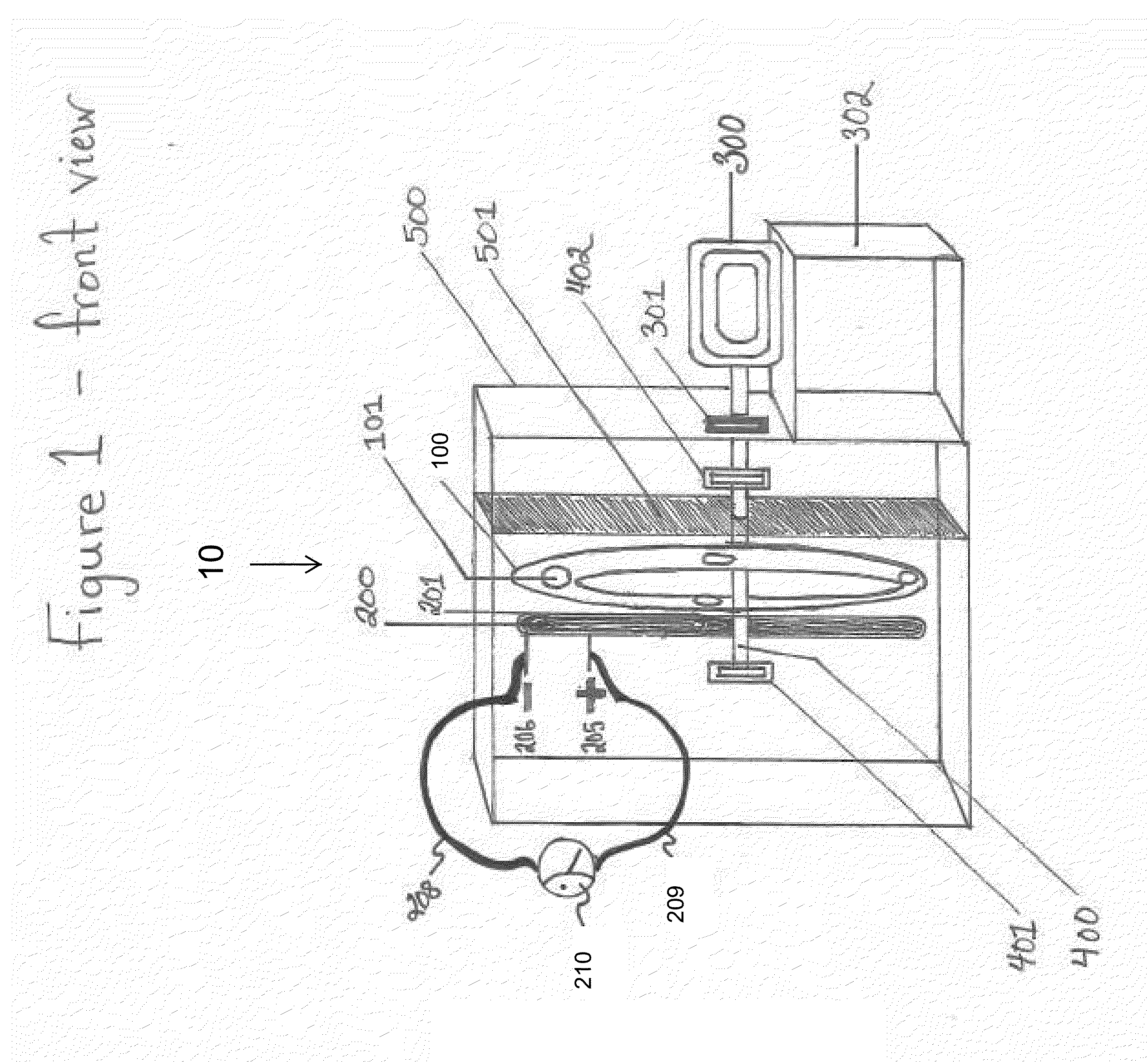
[0004]Embodiments of the invention provide a stationary coil or coils positioned by or above or below or beside a magnet or a plate face magnet with one or more magnets (similar to an inner arrangement of a Shurite amp meter). One embodiment provides a generator device comprising one of at least one imbedded magnets or at least one imbedded coils held in a frame. In this embodiment, but not limited to this embodiment, the frame comprises a round holding plate comprising recesses wherein one or more than one magnets may be received, or one coil or more than one coils may be received). In the embodiment, the holding plate is fastened to a metal rod or shaft or two metal rods or shafts, which balance the holding plate on bearings at the ends of the shaft or shafts which are attached by the use of bearings and couplings. In the embodiment, the bearings are fastened to the walls of the generator frame such that when the coil(s) or magnet(s) rotate, the coil(s) or magnet(s) are balanced. In the embodiment, motion is induced at a speed in the plate holding the magnet(s) or coil(s) by a motor turning or rotating a rod or shaft attached to the motor at a proximate end and to the rod or shaft fastened to the holding plate at a distal end. The motor turns and / or rotates the holding plate magnet(s) or coil(s), which ultimately causes the induction of electric current when the magnet(s) or coil(s) cut across field or flux lines of one or more stationary coil(s) or magnet(s), respectively, within or around the frame. In related embodiments, the stationary magnet(s) may be provided in a variety of shapes and sizes and held in or around the frame so that when motion is induced in the magnet(s) or coil(s) held on the plate, the motion induces the production of an electric field and electric current.
[0005]In a first aspect of the present invention, an electrical energy generator device is provided , comprising: a rotating plate apparatus, the rotating plate apparatus having an axis of rotation; at least one metal coil disposed on the rotating plate apparatus; at least one stationary magnet, a magnetic flux field of the magnet being in contact with the metal coil; a driving shaft secured to the rotating plate apparatus along the axis of rotation; a mechanical movement delivery device secured to the driving shaft, and a set of gears having a least a two-to-one gear ratio in mechanical contact with the rotating plate apparatus and the mechanical movement delivery device via the driving shaft and being configured to increase torque along the driving shaft, wherein energy is generated when the metal coil passes through the magnetic flux field of the magnet, and wherein a voltage of the generated energy is proportionate to a gear ratio of the set of gears.
[0006]In another aspect of the present invention, an electricity generator is provided, comprising: a rotating plate apparatus, the rotating plate apparatus having an axis of rotation; at least one magnet disposed on the rotating plate apparatus; at least one stationary metal coil, a magnetic flux field of the magnet being in contact with the metal coil; an at least two-part driving shaft, a first part secured to a first side of the rotating plate apparatus and a second part secured to a second side of the rotating plate apparatus along the axis of rotation; a mechanical movement delivery device secured to the driving shaft, and a set of gears having a least a two-to-one gear ratio in mechanical contact with the rotating plate apparatus and the mechanical movement delivery device via the driving shaft and being configured to increase torque along the driving shaft, wherein energy is generated when the magnetic flux field of the magnet passes through the metal coil, and wherein a voltage of the generated energy is proportionate to a gear ratio of the set of gears.
[0007]In yet another aspect of the present invention, an electrical voltage generator is provided, comprising: a rotating coil apparatus disposed to rotate within an outer frame; a motor mechanically attached to the rotating coil apparatus; a stationary neodymium magnet disposed within the rotating coil apparatus; a first electrical wire in electrical contact with a first end of the rotating coil apparatus; a second electrical wire in electrical contact with second end of the rotating coil apparatus, the first and second wires forming a closed circuit having a load; a set of gears having a least a two-to-one gear ratio in mechanical contact with the rotating coil apparatus and the motor and being configured to increase torque along the driving shaft; and a protective partition plate disposed between the stationary neodymium magnet and the motor, wherein the motor has an initial voltage and the load registers an output voltage, and the output voltage is based on a gear ratio of the set of gears.

Problems solved by technology

In general, windmills used to capture wind energy continue to prove costly, from complex manufacturing methods and the weight of requisite materials.
Solar panels, in general, also provide a cost-ineffective source of energy, from expensive materials to undependable weather patterns.

Method used


Image

  • Alternative energy generator
  • Alternative energy generator

Examples


Embodiment Construction

[0011]Illustrative embodiments will now be described more fully herein with reference to the accompanying drawings, in which embodiments are shown. This disclosure may, however, be embodied in many different forms and should not be construed as limited to the embodiments set forth herein. Rather, these embodiments are provided so that this disclosure will be thorough and complete and will fully convey the scope of this disclosure to those skilled in the art. In the description, details of well-known features and techniques may be omitted to avoid unnecessarily obscuring the presented embodiments.

[0012]The terminology used herein is for the purpose of describing particular embodiments only and is not intended to be limiting of this disclosure. As used herein, the singular forms “a”, “an”, and “the” are intended to include the plural forms as well, unless the context clearly indicates otherwise. Furthermore, the use of the terms “a”, “an”, etc., do not denote a limitation of quantity,...


PUM


Abstract

Approaches presented herein enable an alternative energy generator to generate electricity and scaled voltage by placing stationary rare earth magnets on a rotating plate in such a manner that an electric current is produced when the magnets on the plate are moved and the magnet flux lines cut across a stationary metal coil. More specifically, one or more stationary metal coils are positioned near a rotating plate on which a set of magnets are places, the metal coils oriented to be crossed by magnetic flux lines of the magnets. Alternatively, a set of magnets or metal coils are place on a rotating plate with one or more stationary magnets oriented near to yield crossed magnetic flux lines. The rotating plate may be driven by a motor, a hand crank, or any human motion with a set of gears to facilitate rotational torque.

Description

RELATED U.S. APPLICATION DATA[0001]The present patent document claims priority to U.S. provisional patent application Ser. No. 62 / 010,698, filed Jun. 11, 2014 and entitled “ALTERNATIVE ENERGY GENERATOR”, the disclosure of which is incorporated herein by reference.FIELD OF THE INVENTION[0002]The present invention relates to a method and apparatus for generating electrical voltage from the motion or rotation of a mechanical apparatus or a motor, and relates more specifically to a method and apparatus for generating electrical voltage from an electromagnetic field.BACKGROUND OF THE INVENTION[0003]Energy may be generated from wind and solar energy sources as well as sources of fossils fuel. Alternative forms of generating electricity are important for many reasons. In general, windmills used to capture wind energy continue to prove costly, from complex manufacturing methods and the weight of requisite materials. Solar panels, in general, also provide a cost-ineffective source of energy,...

Claims


Application Information

Patent Timeline
Patent Type & Authority Applications(United States)
IPC IPC(8): H02K7/116H02K1/27
CPCH02K1/2793H02K7/116H02K21/24
Inventor FARQUHARSON, ASTON GUSTAVOUS
Owner FARQUHARSON ASTON GUSTAVOUS
Why Eureka
Try Eureka