Image relaying cannula with detachable self-aligning connector

a self-aligning connector and image relaying technology, applied in the field of biological microscopy, can solve the problem that large objectives cannot be implanted within a sample without causing significant damage to the sampl

Active Publication Date: 2015-12-24
OPTOMAK
View PDF3 Cites 6 Cited by
  • Summary
  • Abstract
  • Description
  • Claims
  • Application Information

AI Technical Summary

Problems solved by technology

However, conventional microscopes feature large size microscope objectives.
Large objectives cannot be implanted within a sample without causing significant damage to the sample, such as removing structures in order to facilitate access to deep layers within the sample.

Method used


Image

  • Image relaying cannula with detachable self-aligning connector
  • Image relaying cannula with detachable self-aligning connector
  • Image relaying cannula with detachable self-aligning connector

Examples


Embodiment Construction

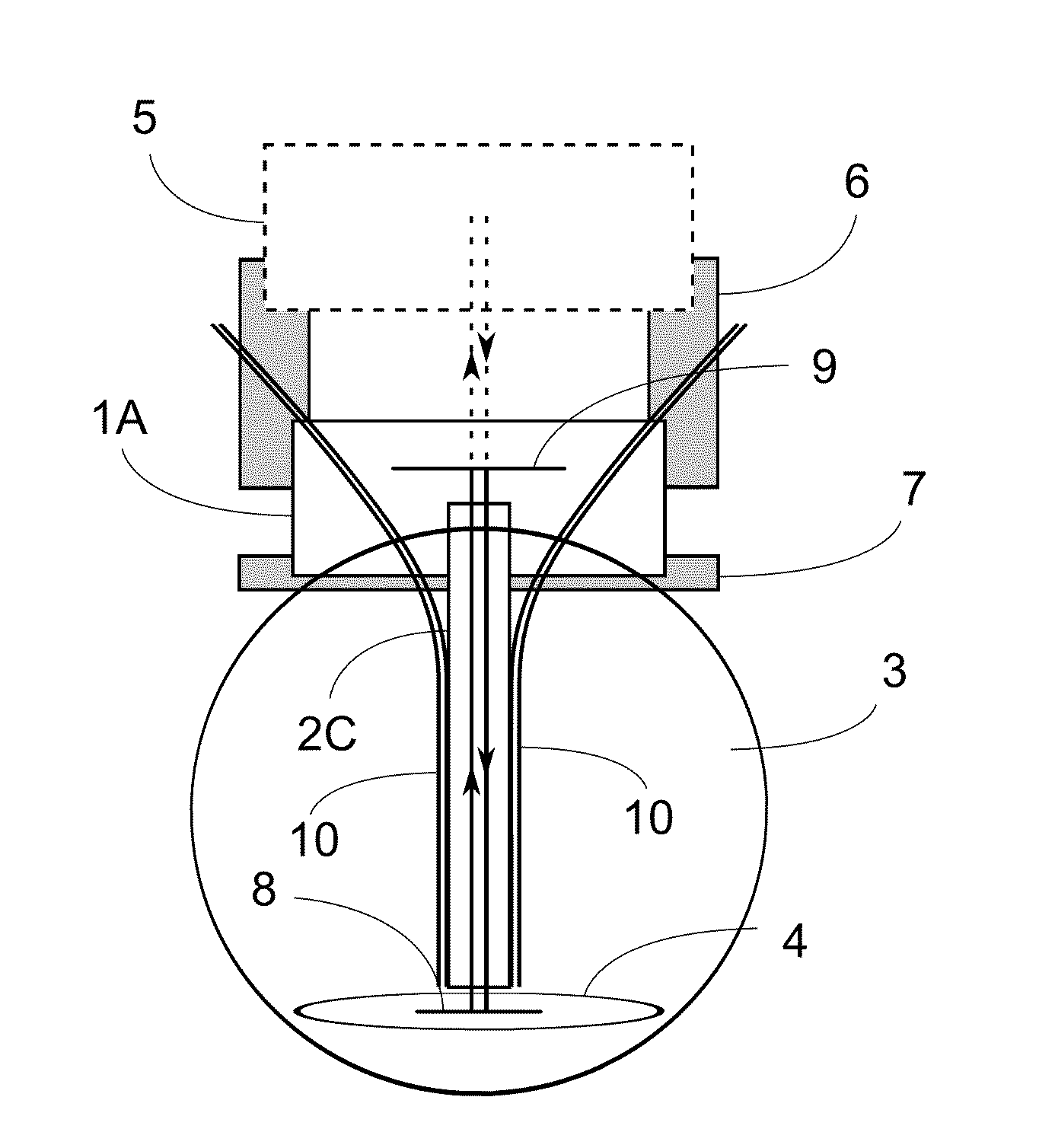
[0018]The present invention concerns an optical cannula for coupling an image taken within a biological sample, generally an in vivo biological sample, to an optical system or device, such as a microscope. In order to provide minimal invasiveness with respect to the sample, but in order to reach deep tissues, the cannula includes an extension portion that projects into the sample and a stabilizer portion at which the cannula is mounted to the sample. The cannula features an optical probe that extends through the extension portion and serves as a relay imaging system that relays an image of structures located at the distal end of the extension portion of the cannula to the proximal end of the probe. The optical cannula can be used for image magnification and recording and may also be coupled to an illumination source to optically excite specific areas within a sample. Alternatively, or in combination the cannula may provide coupling for electrodes for electrical stimulation or measur...


PUM


Abstract

An optical cannula configured for implantation in biological tissue or other samples provides minimal invasiveness while accessing image deep structures within the sample. The cannula has a stabilizer portion that is used to affix the cannula to the sample, and an extension portion that protrudes into the sample and is either formed by, or contains, an optical probe that images a target area within the sample to an object image provided to an external optical device. The cannula has an integrated coupler portion that detachably connects to a connector of the external device, providing removable and interchangeable connection to external optical systems.

Description

BACKGROUND OF THE INVENTION[0001]1. Field of the Invention[0002]The present invention is related generally to biological microscopy, and in particular to a cannula for detachably connecting and aligning an optical device to a biological sample.[0003]2. Background of the Invention[0004]When making microscopic observations of in vivo biological specimens, minimally invasive techniques are required. However, conventional microscopes feature large size microscope objectives. Large objectives cannot be implanted within a sample without causing significant damage to the sample, such as removing structures in order to facilitate access to deep layers within the sample. Less invasive fiber-optic cannulae that are typically used in optogenetics experiments are typically configured only for optical stimulation or silencing of a certain class of neurons.[0005]Existing optical devices that relay an image outside of a sample are either implanted directly in the sample or inserted in a metallic t...

Claims


Application Information

Patent Timeline
Patent Type & Authority Applications(United States)
IPC IPC(8): A61B1/00A61B5/053A61B1/015A61B5/00
CPCA61B1/00126A61B5/0084A61B1/015A61B5/0538A61B1/00167A61B1/0615A61B5/0071A61B5/6865A61B5/688A61B2560/0443A61B2562/228
Inventor LABRIE, JONATANDEHEZ, HAROLDDORIC, SEAD
Owner OPTOMAK
Why Eureka
Try Eureka