Pulse wave velocity measurement method
a pulse wave velocity and measurement method technology, applied in the field of pulse wave velocity measurement method and system as well as imaging device, can solve the problems of increasing cost, difficult to be widely used for general users, and difficulty in providing various functions, so as to improve the measurement accuracy of pulse wave velocity and low cost
- Summary
- Abstract
- Description
- Claims
- Application Information
AI Technical Summary
Benefits of technology
Problems solved by technology
Method used
Image
Examples
first embodiment
[0043]First, the description focuses on the outline of a pulse wave velocity system according to a first embodiment of the present invention.
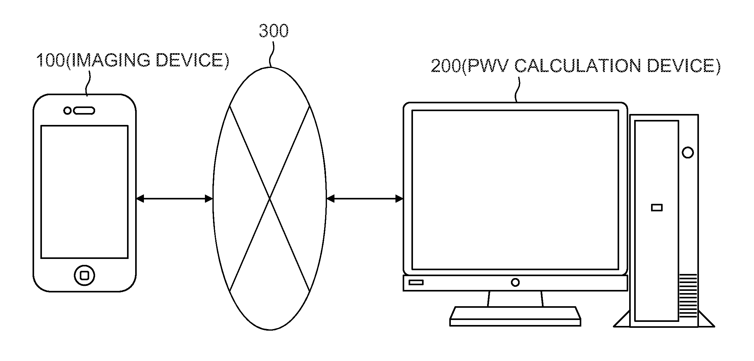
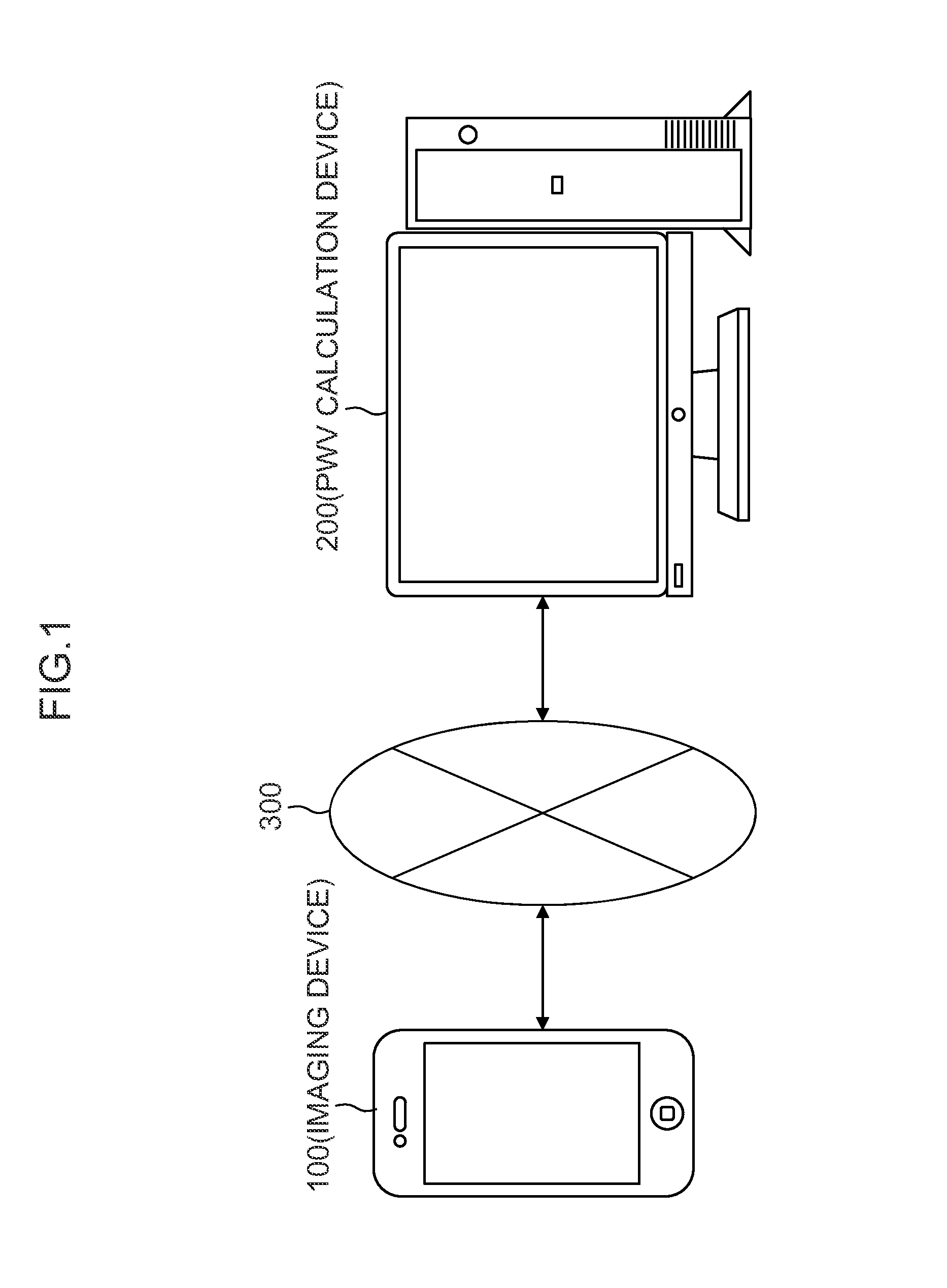
[0044]FIG. 1 is a schematic view illustrating an entire configuration of the pulse wave velocity measurement system according to the present embodiment. As illustrated in FIG. 1, the pulse wave velocity measurement system of the present embodiment includes an imaging device 100 and a pulse wave velocity calculation device (hereinafter referred to as “a PWV calculation device”) 200. The imaging device 100 and the PWV calculation device 200 are connected to each other so that various data can be transmitted and received through a network 300 such as the Internet.
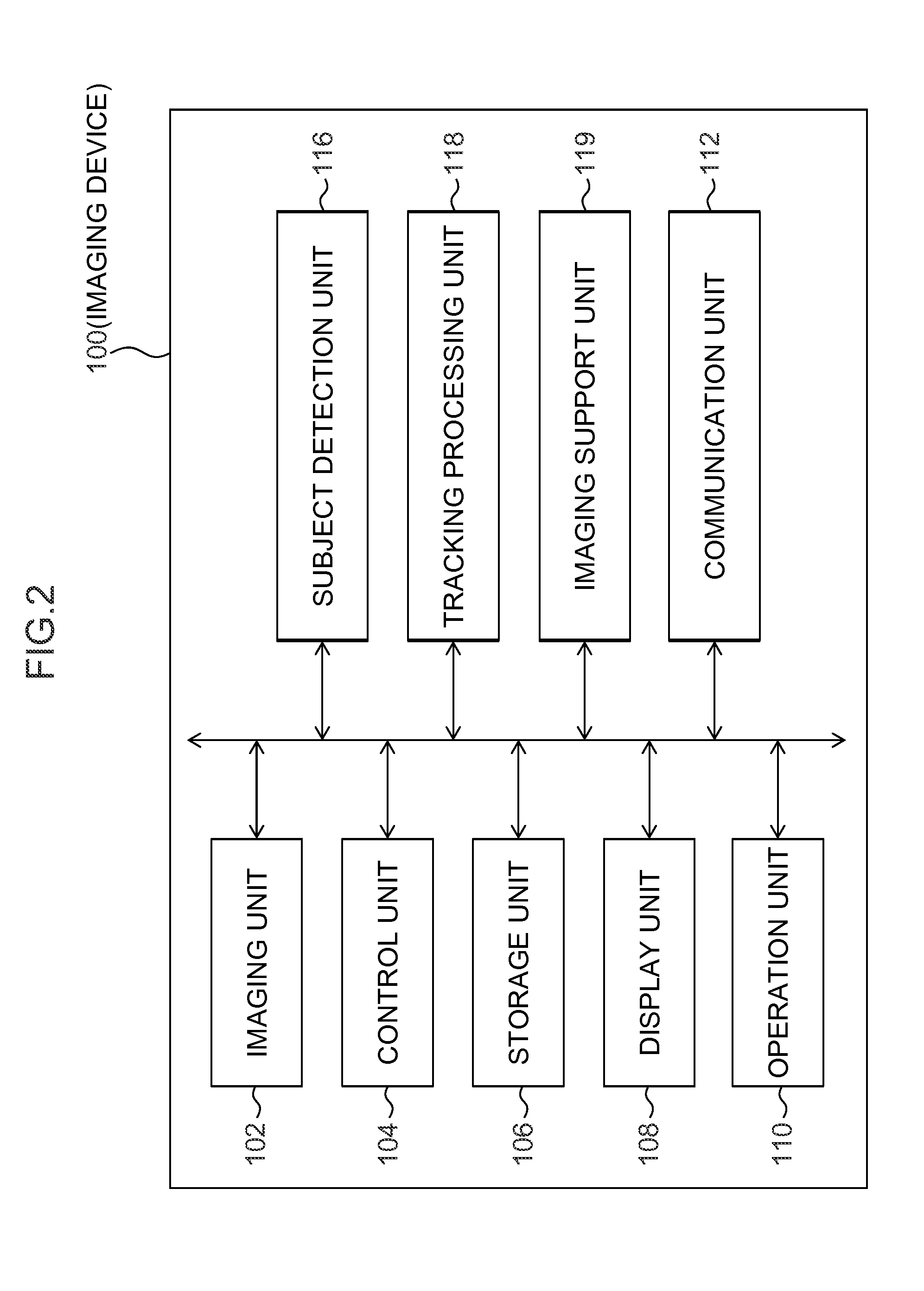
[0045]The imaging device 100 is constituted by a terminal device having a typical imaging function (visible light camera) such as a smartphone, a camera mobile phone, a digital camera, a video camera, and a Web camera. The present embodiment assumes that the imaging device 100 is a smartp...
second embodiment
[0114]Now, the description focuses on a second embodiment of the present invention. Note that the description of the components common to the first embodiment is omitted and the following description will mainly focus on the characteristic components of the present embodiment.
[0115]FIG. 21 is a block diagram illustrating a configuration of the calculation unit 212 of the PWV calculation device 200 according to the second embodiment. It should be noted that in FIG. 21, the same reference numbers are assigned to the components common to FIG. 8, and the description thereof is omitted.
[0116]According to the second embodiment, the calculation unit 212 includes a reference region detection unit 234 which detects a temporal variation (color change in skin) of a pixel value in a reference region in order to detect the light amount of illumination light or a temporal variation in color from each frame image. Note that the reference region detection unit 234 is a processing unit for performin...
PUM
 Abstract
Description
Claims
Application Information
 - R&D
- Intellectual Property
- Life Sciences
- Materials
- Tech Scout
- Unparalleled Data Quality
- Higher Quality Content
- 60% Fewer Hallucinations
Browse by: Latest US Patents, China's latest patents, Technical Efficacy Thesaurus, Application Domain, Technology Topic, Popular Technical Reports.
© 2025 PatSnap. All rights reserved.Legal|Privacy policy|Modern Slavery Act Transparency Statement|Sitemap|About US| Contact US: help@patsnap.com


