Ophthalmic treatment apparatus and method for controlling same

a technology of ophthalmic treatment and control device, which is applied in the field of ophthalmic treatment apparatus and control device, can solve the problems of inability to effectively treat patients, and achieve the effect of improving treatment efficiency and accurate treatmen

Inactive Publication Date: 2015-12-24
LUTRONIC VISION INC
View PDF5 Cites 5 Cited by
  • Summary
  • Abstract
  • Description
  • Claims
  • Application Information

AI Technical Summary

Benefits of technology

[0013]The ophthalmic treatment apparatuses and the methods of controlling the same according to the present invention are advantageous in that accurate treatment is possible and treatment efficiency can be improved because an image of the subject to be treated is captured and the location to which a beam for treatment is radiated is determined based the captured image or the radiation location is determined using tissue characteristics.

Problems solved by technology

However, the technical characteristic disclosed in the conventional prior document controls the location to which laser light is radiated using the viewing device and the location control means, but has a disadvantage in that effective treatment is impossible because it is difficult to set an accurate lesion region.

Method used


Image

  • Ophthalmic treatment apparatus and method for controlling same
  • Ophthalmic treatment apparatus and method for controlling same
  • Ophthalmic treatment apparatus and method for controlling same

Examples


second embodiment

[0063]FIG. 8 is a control flowchart illustrating a method of controlling the ophthalmic treatment apparatus in accordance with the second embodiment of the present invention.

[0064]The method of controlling the ophthalmic treatment apparatus 1010 in accordance with the second embodiment of the present invention is described below with reference to FIG. 8.

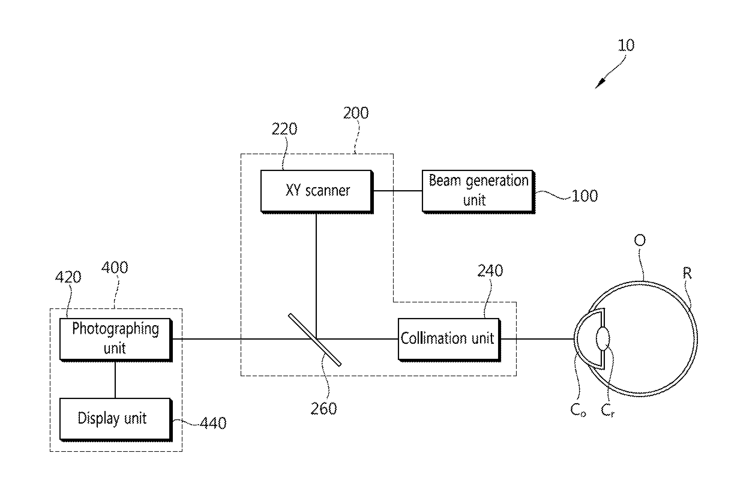
[0065]First, the image unit 1400 operates and forms an image of the eyeball O by photographing the eyeball O. The beam generation unit 1100 generates an alignment beam and radiates the alignment beam to the treatment region of the eyeball O (S1010). In this case, the alignment beam preferably has a wavelength band different from that of beams for treatment and has a wavelength band having a high degree of water sorption.

[0066]When the alignment beam is radiated to the treatment region of the eyeball O at step ‘S1010’, whether the tissue state of the eyeball O is changed is detected (S1030). If a change of the tissue state in the trea...

third embodiment

[0068]FIG. 9 is a control flowchart illustrating a method of controlling the ophthalmic treatment apparatus in accordance with the third embodiment of the present invention.

[0069]The method of controlling the ophthalmic treatment apparatus 1010 in accordance with the third embodiment of the present invention is described below in detail with reference to FIG. 9.

[0070]First, when the image unit 1400 is driven, it generates an image of the eyeball O by photographing the eyeball O. Furthermore, an alignment beam is radiated to the treatment region of the eyeball O based on the image of the eyeball O generated by the image unit 1400 (S1100). In this case, as in the second embodiment, the alignment beam radiated to the treatment region of the eyeball O preferably has a wavelength band different from that of beams for treatment and has a wavelength band having a high degree of water sorption.

[0071]When the alignment beam is radiated, the tissue detection unit 1800 detects whether the tiss...


PUM


Abstract

The present invention relates to an ophthalmic treatment apparatus and to a method for controlling same. The ophthalmic treatment apparatus according to the present invention comprises: a beam generating unit for generating a treatment beam; an image unit for generating an image of an eyeball to be treated and displaying the image of the eyeball; an input unit for applying an input signal so as to display a lesion region in the image of the eyeball displayed by the image unit; and a control unit for controlling the operation of the beam generating unit such that the treatment beam can be radiated onto the lesion region in accordance with the lesion region displayed by means of the input signal inputted by the input unit.

Description

BACKGROUND OF THE INVENTION[0001]1. Field of the Invention[0002]The present invention relates to an ophthalmic treatment apparatus and a method of controlling the same and, more particularly, to an ophthalmic treatment apparatus for treating ocular diseases and a method of controlling the same.[0003]2. Related Art[0004]An ophthalmic treatment apparatus is an apparatus for radiating beams for treatment in order to treat glaucoma, a cataract, or macular degeneration generated in an eyeball. In this case, from among ocular diseases, glaucoma is attributable to an increase in the intraocular pressure of vitreous humour, a cataract is attributable to the whitening phenomenon of the crystalline lens, and macular degeneration is generated in the retina.[0005]This ophthalmic treatment apparatus captures an image of an eyeball in order to identify a region in which an ocular disease has occurred. Furthermore, the ophthalmic treatment apparatus radiates a beam for treatment to the lesion regi...

Claims


Application Information

Patent Timeline
Patent Type & Authority Applications(United States)
IPC IPC(8): A61F9/008
CPCA61F9/008A61F2009/00851A61F2009/00885A61F2009/00891A61F2009/00844A61F2009/00887A61B3/14
Inventor HA, TAE HOHAN, KWANG SUKIM, EUN KYOUM
Owner LUTRONIC VISION INC
Why Eureka
Try Eureka