

Percussive massage device with force meter
a technology of force meter and massage device, which is applied in the direction of vibration massage, force/torque/work measurement apparatus, instruments, etc., can solve the problems of difficulty in users to know if they are applying the proper amount of pressure or force, and achieve precise and personalized treatment, reduce vibrational sound, and improve the effect of massage
- Summary
- Abstract
- Description
- Claims
- Application Information
AI Technical Summary
Benefits of technology
Problems solved by technology
Method used
Image

Examples
Embodiment Construction
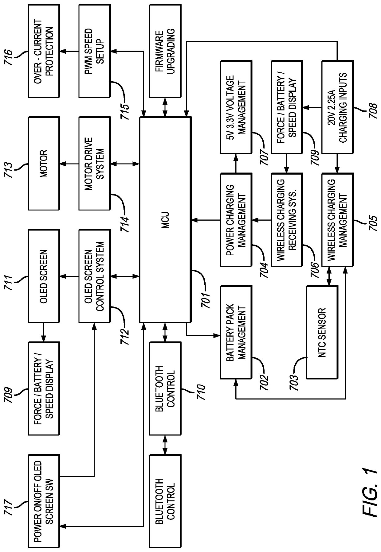
[0004]In accordance with a first aspect of the present invention there is provided a percussive massage device with a force meter that includes a housing, an electrical source, a motor positioned in the housing, a switch for activating the motor, and a controller configured to obtain a voltage of the motor, generate a lookup table correlating voltage to force applied by the percussive massage device, and display a force magnitude corresponding to the obtained voltage using the lookup table. In a preferred embodiment, the lookup table is generated by determining a maximum magnitude of force configured to be applied by the percussive massage device, determining a maximum magnitude of voltage configured to be applied to the percussive massage device from a power source, dividing the maximum magnitude of force into equal force increments, and dividing the maximum magnitude of voltage into equal voltage increments. The number of equal force increments and the number of equal voltage incr...
PUM
| Property | Measurement | Unit |
|---|---|---|
| frequency | aaaaa | aaaaa |
| frequency | aaaaa | aaaaa |
| frequency | aaaaa | aaaaa |
Abstract
Description
Claims
Application Information