Three dimensional printer

Active Publication Date: 2015-12-24
SODICK CO LTD
View PDF5 Cites 61 Cited by
  • Summary
  • Abstract
  • Description
  • Claims
  • Application Information

AI Technical Summary

Benefits of technology

[0013]In the present invention, an inert gas having the same composition as the inert gas in the molding space of the chamber is used as the inert gas filled in the housing provided in the fume diffusing section of the chamber. In addition, the inert gas in the housing is discharged from an opening provided on the housing as a streamline flow flowing along the optical pathway of the laser beam. According to such constitution, the inert gas can be removed from the optical pathway of the laser beam by the streamline flow of the inert gas. In addition, the inert gas environment in the molding space can be easily maintained by using inert gas having the same composition as the inert gas in the housing of the fume diffusing section for the inert gas in the molding space.
[0014]Hereinafter, various embodiments of the present invention will be provided. The embodiments provided below can be combined with each other.
[0015]Preferably, the fume diffusing section comprises a diffusing member provided in the housing so as to surround the opening; the diffusing member comprises a plurality of fine pores; and the inert gas supplying pathway is provided in between the housing and the diffusing member, and the inert gas is discharged from the opening through the fine pores.
[0016]Preferably, a temperature of the inert gas in the housing is substantially the same as a temperature of the inert gas in the molding space.
[0017]Further preferably, a lamination molding apparatus, comprising: a chamber having a molding space covering a desired molding region and being filled with an inert gas of a predetermined concentration; a fume diffusing section arranged on an upper surface of the chamber so as to cover a window prov

Problems solved by technology

However, such removal is still insufficient.
In particular, when the laser beam is emitted from the upper side of the chamber, even a sca

Method used


Image

  • Three dimensional printer
  • Three dimensional printer
  • Three dimensional printer

Examples


Embodiment Construction

[0028]Hereinafter, the embodiments of the present invention will be described with reference to the drawings. Here, the characteristic matters shown in the embodiments can be combined with each other.

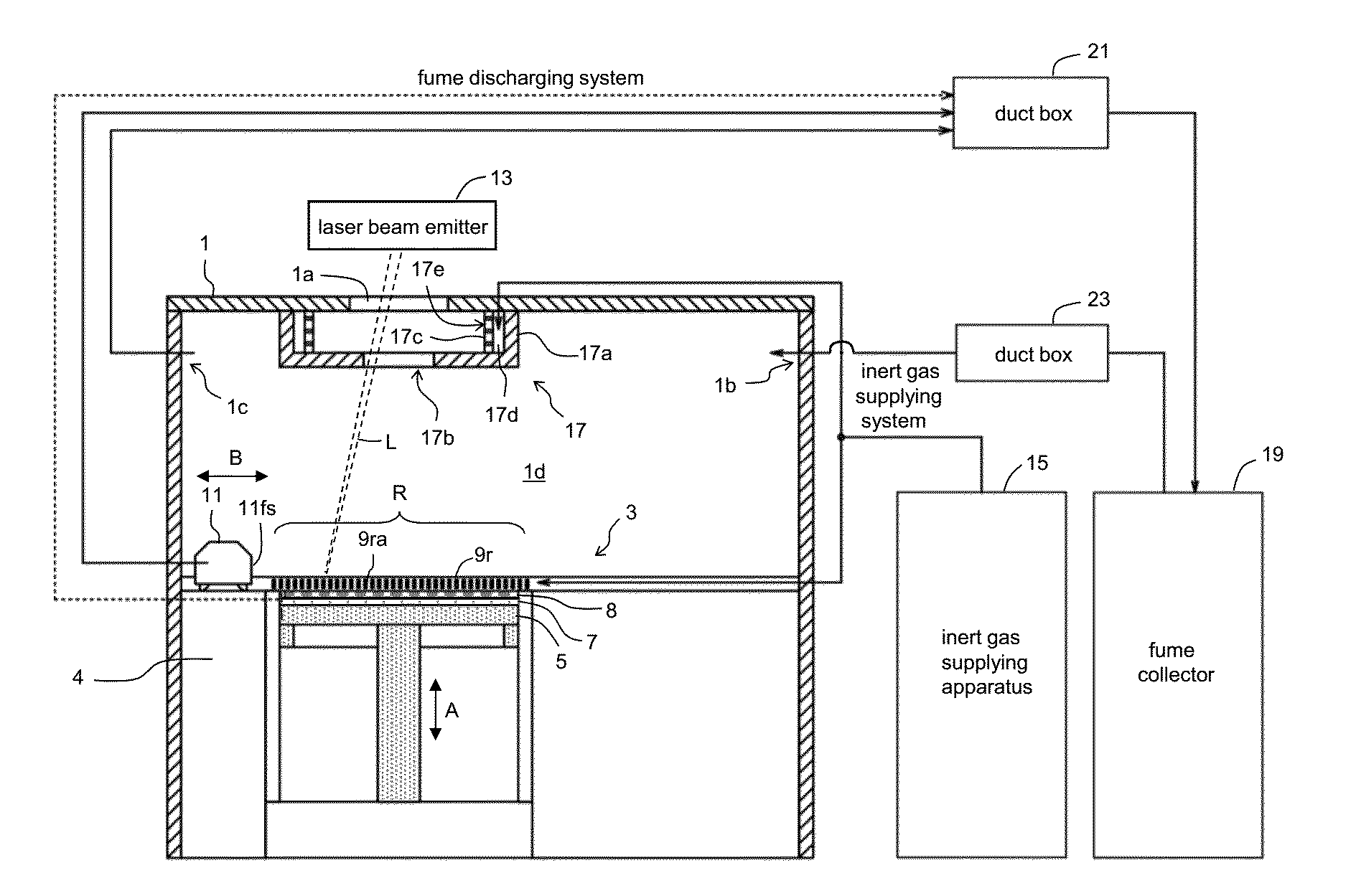
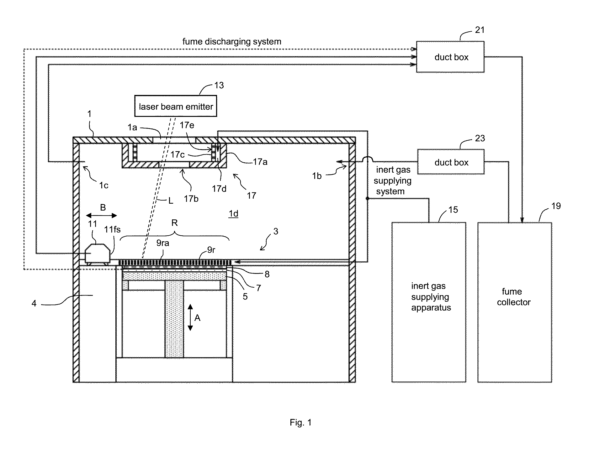
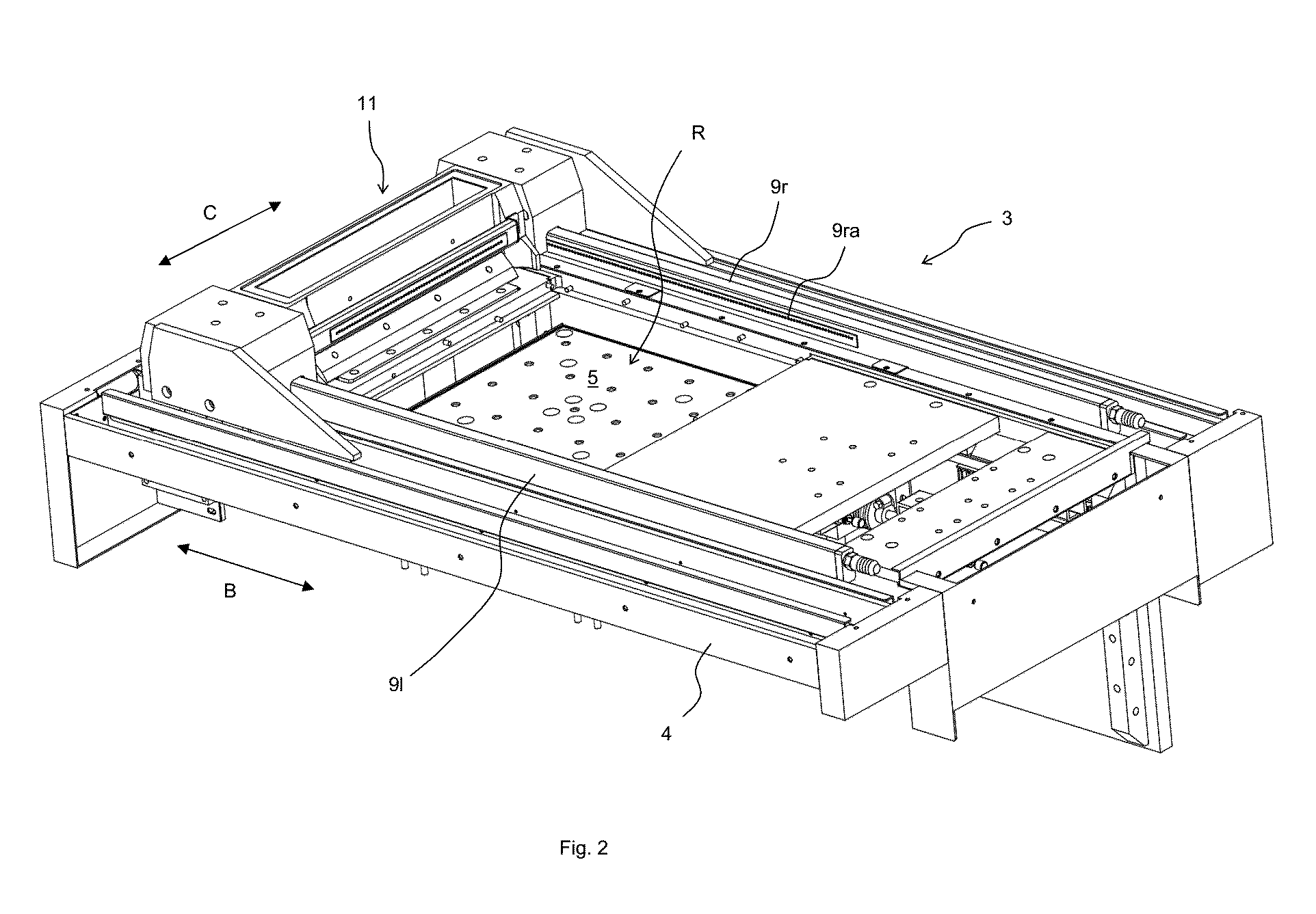
[0029]As shown in FIGS. 1 and 2, the lamination molding apparatus according to one embodiment of the present invention is structured by providing the powder layer forming apparatus 3 in the chamber 1. The powder layer forming apparatus 3 comprises a base 4 having a molding region R, a recoater head 11 provided on the base 4 and being capable of moving in a horizontal uniaxial direction (direction shown by arrow B), and elongated members 9r and 91 provided on both sides of the molding region R along the moving direction of the recoater head 11. The molding region R is provided with a molding table 5 capable of moving vertically (direction shown by arrow A in FIG. 1). When the lamination molding apparatus is used, the molding plate 7 is arranged on the molding table 5, and the material po...


PUM

PropertyMeasurementUnit
Temperatureaaaaaaaaaa

Abstract

An improved lamination molding apparatus which can maintain the inert gas environment in the chamber as well as remove the fume swiftly and efficiently away from the optical pathway of the laser beam, is provided.

Description

BACKGROUND OF THE INVENTION[0001]1. Field of the Invention[0002]The present invention relates to a lamination molding device.[0003]2. Background of the Invention[0004]In a powder sintering / laminating method (laser lithography) of metal using laser beam, a particular smoke known as fume is generated when the metal material powder is irradiated with laser beam for sintering. When the chamber gets filled with fume, the fume may shield the laser beam, and the laser beam with necessary energy may not reach the sintering portion.[0005]Current laser lithography apparatus (sintering lamination molding apparatus) for molding metal products is generally operated by supplying the material powder in a chamber filled with inert gas (usually nitrogen gas), followed by irradiation of the material powder with the laser beam.[0006]In order to stably emit the laser beam, it is necessary to maintain the concentration of the inert gas in the chamber at a constant level. Accordingly, constitution is mad...

Claims


Application Information

Patent Timeline
IPC IPC(8): B29C67/00
CPCB33Y30/00B29C67/0077B29C64/153B29C64/268B29C64/371Y02P10/25B22F12/38B22F12/49B22F10/32B22F10/28B22F12/41B22F10/77
Inventor ARAIE, ICHIROMURANAKA, KATSUTAKAKAWADA, SHUICHIOKAZAKI, SHUJI
Owner SODICK CO LTD
Why Eureka
Try Eureka