
Slide valve

a technology of sliding valve and sliding plate, which is applied in the direction of valve details, multiple way valves, thin material handling, etc., can solve the problems of consuming energy of the valve drive, requiring installation space, and being difficult to make it more compact, etc., and achieves the effect of less energy

Active Publication Date: 2015-12-24
BURKERT WERKE
View PDF6 Cites 5 Cited by
  • Summary
  • Abstract
  • Description
  • Claims
  • Application Information

AI Technical Summary

Benefits of technology

The invention is a slide valve that uses a polymer actuator to adjust the slide and switch fluids. The actuator uses the properties of polymers that deform when an electric voltage is applied, resulting in a compact construction. The actuator does not contain any ferromagnetic materials, making it suitable for high-field magnetic applications. The technical effects are that the slide valve requires little energy to adjust, can switch multiple fluids with a single actuator, and can be used even in high-field magnetic applications.

Problems solved by technology

A problem with conventional slide valves is that the valve drive used generally consumes energy even when stationary.
A further problem which occurs in slide valves is the required installation space.
In particular, if there is an electromagnetic drive, it is scarcely possible to make it more compact.
However, drives of this type are very complex (for example because of a required stroke transmission) if they are able to produce a sufficiently large adjustment distance, such as is required for a slide valve.

Method used


Image

  • Slide valve
  • Slide valve
  • Slide valve

Examples


first embodiment

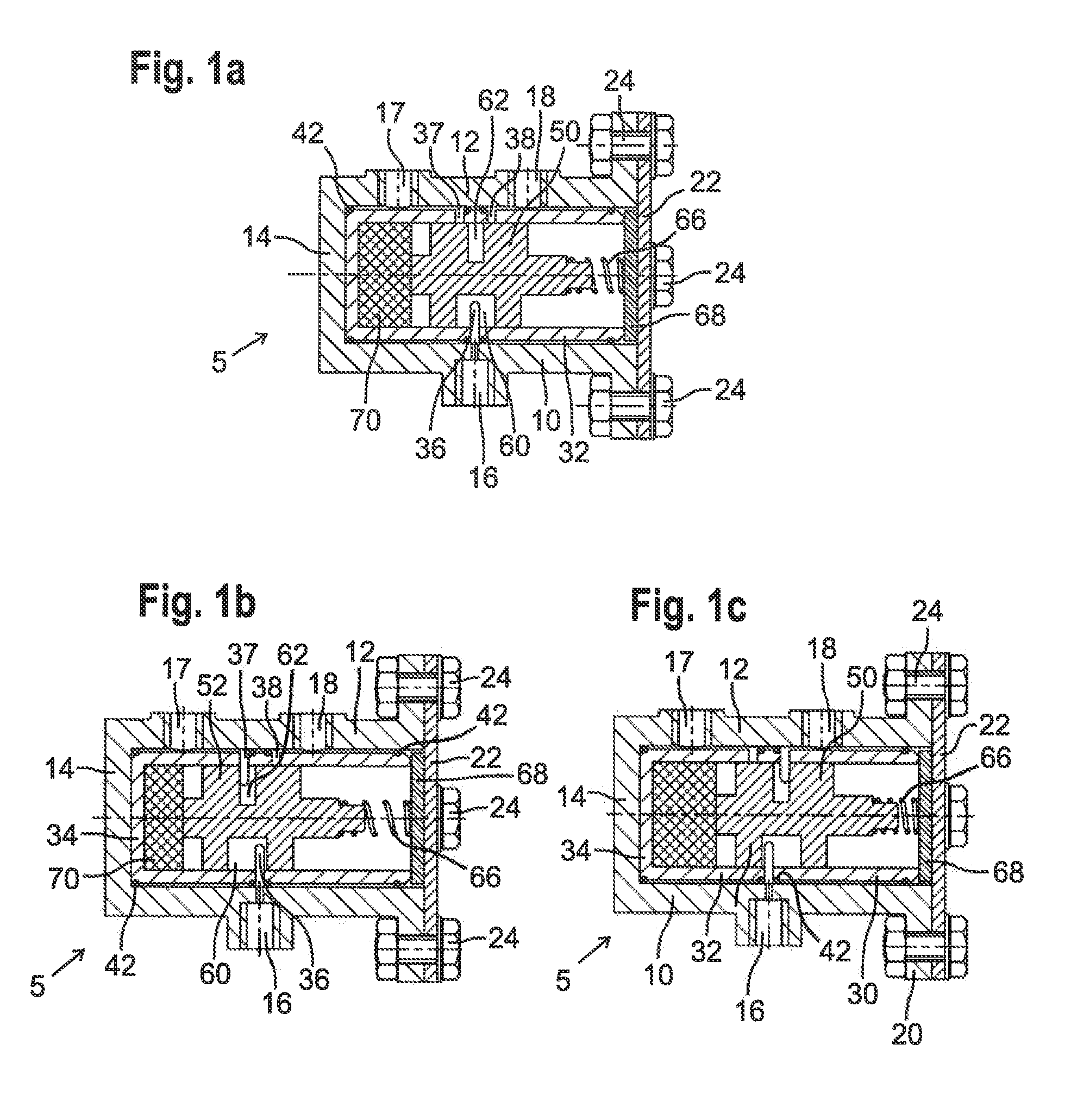
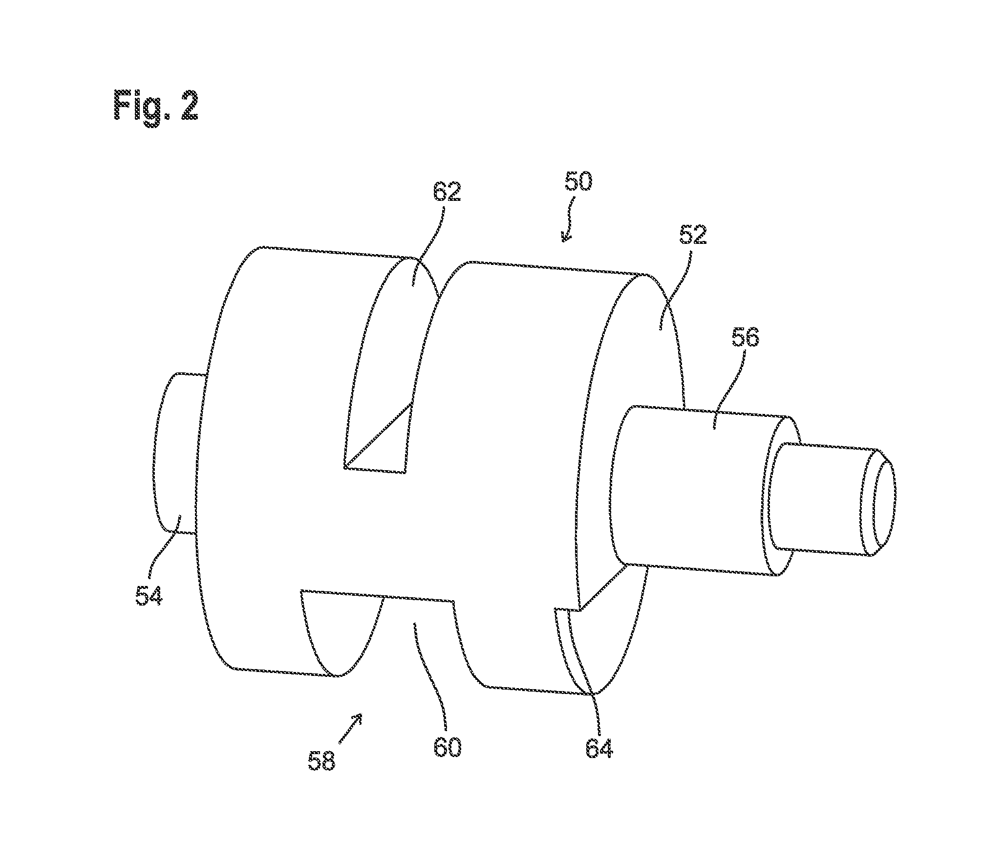
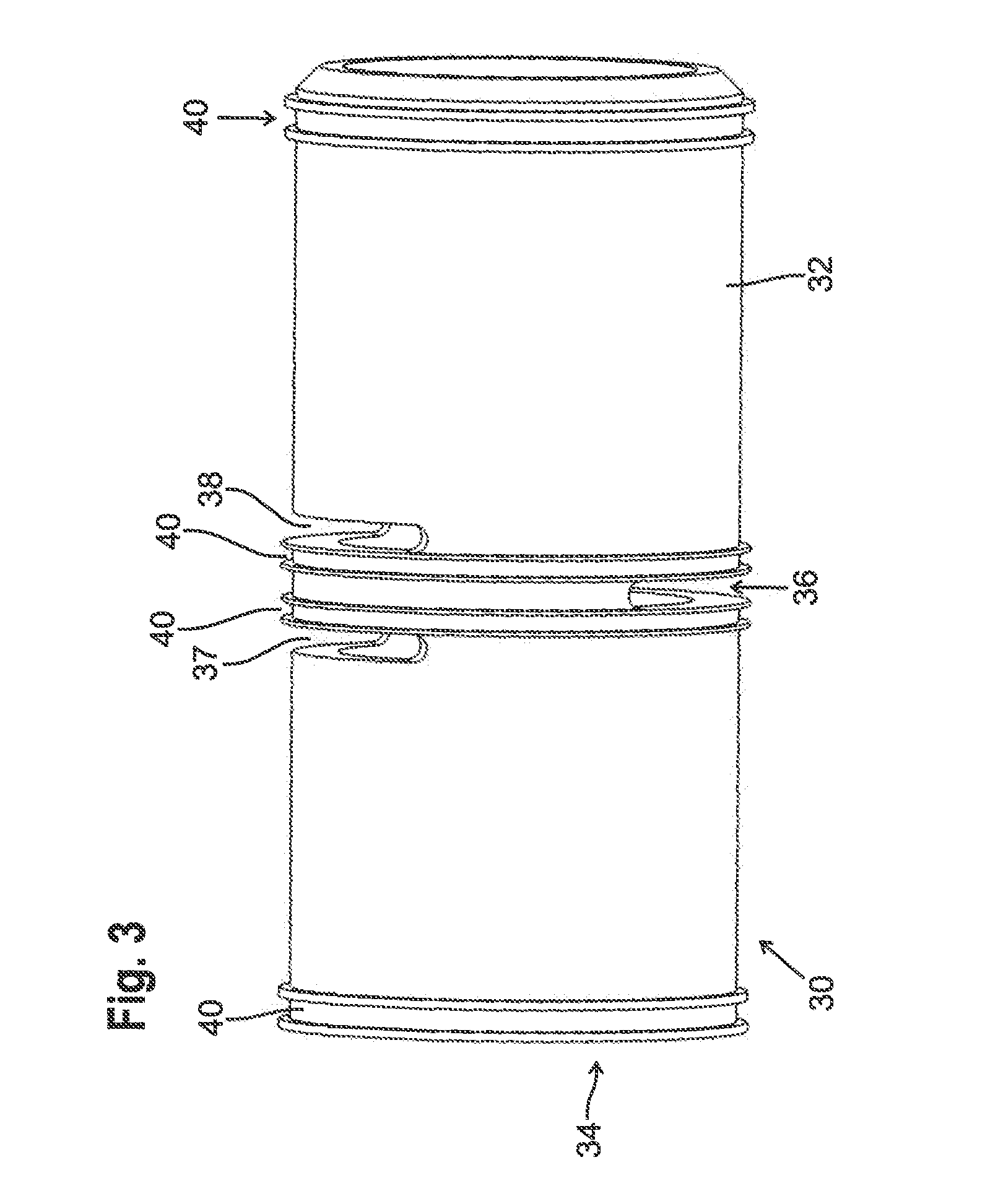
[0076]In the following, the polymer actuator 70 is disclosed by way of FIGS. 4 to 6. The slide valve 5 basically corresponds to the embodiment shown in FIGS. 1 to 3, and like reference numerals are used for the components known from this embodiment. All of the explanations regarding these components also apply to the slide valve of FIGS. 4 to 6.

[0077]In the embodiment of FIGS. 4 to 6, the polymer actuator 70 is a dielectric elastomer actuator, which in this case is in the form of a membrane actuator.

[0078]The dielectric polymer actuator is generally based on the application of a large-area electrode to each of two mutually opposing faces of a dielectric polymer film. When a sufficiently high electric voltage is applied to the electrodes, the electrodes attract one another, in such a way that the interposed film is compressed. Since the dielectric film used is virtually incompressible, the reduction in the distance between the electrodes leads to a change in shape. In a membrane, for...

second embodiment

[0092]FIG. 8 to 9 show the polymer actuator 70. Aside from the changes to the polymer actuator, the valve corresponds to the one known from FIGS. 1 to 6. Accordingly, the components known from these drawings are provided with like reference numerals, and reference is made to the relevant explanations.

[0093]The difference from the polymer actuator of the embodiment of FIGS. 4 to 65 is that a stack actuator is used in the embodiment of FIGS. 8 and 9. A stack actuator consists of a plurality of individual layers of dielectric polymer film, in such a way that a dielectric elastomer actuator is again formed. The electrodes on the mutually remote faces of each layer are mutually contacted, in such a way that an electric voltage can be applied between the electrodes on the mutually remote faces of a layer. Under the action of this voltage, the respective layer is compressed, some material being pressed outwards because of the incompressibility of the polymer material used. Overall, the axi...


PUM


Abstract

A slide valve comprises a bushing in which fluid openings are provided which extend through the wail of the bushing, a slide which is arranged adjustably in the bushing and is provided with at least one fluid duct, and an electroactive polymer actuator which can adjust the slide in the bushing.

Description

[0001]The invention relates to a slide valve, by means of which fluid flows can be controlled or switched.BACKGROUND OF THE INVENTION[0002]Slide valves are known in many constructions in the art. They are distinguished in that smaller forces are required for actuating the valve side than in what are known as seat valves, in which a valve element cooperates with a valve seat. The lower forces in a slide valve basically result from the fact that the slide is adjusted perpendicular to the flow direction of the controlled fluid, and therefore, ignoring friction, the pressure of the controlled fluid has a much smaller effect on the required adjusting force.[0003]A problem with conventional slide valves is that the valve drive used generally consumes energy even when stationary. For example, the coil of an electromagnetic valve drive has to be excited continuously during the operation of the slide valve so as to hold the slide in the desired position.[0004]A further problem which occurs i...

Claims


Application Information

Patent Timeline
IPC IPC(8): F16K11/07F16K31/02
CPCF16K11/07Y10T137/86879Y10T137/86863F16K31/02F16K31/008
Inventor RODEGHERI, CRICIA DE CARVALHOKRIPPNER, PETERSEELECKE, STEFAN
Owner BURKERT WERKE
Learn More