Measurement device and purge gas flow rate measuring method

a technology of flow rate measurement and measurement device, which is applied in the direction of fluid speed measurement, liquid/fluent solid measurement, instruments, etc., can solve the problems of purge gas being likely to leak, insufficient air tightness between the nozzle and the gas introduction section,

Active Publication Date: 2015-12-24
MURATA MASCH LTD
View PDF3 Cites 9 Cited by
  • Summary
  • Abstract
  • Description
  • Claims
  • Application Information

AI Technical Summary

Benefits of technology

[0013]Furthermore, it is preferable that the measurement device further includes elastic bodies configured to apply elastic forces downward to the legs; and adjustment members configured to adjust the elastic forces. Also, an adjustment step for the adjustment members adjusting the load applied to the nozzle via the substrate from the gas introduction section is executed. By adjusting the elastic forces to the elastic bodies with the adjustment members in this step, the load applied to the gas introduction section is adjustable in a wide range, and the purge gas flow rate is measured in a carrier in which a small number of articles are housed and in a carrier in which a large number of articles are housed.

Problems solved by technology

For example, a variation in the state of the supply line, specifically, a variation in blockage of members such as pipes, in-line filters, and the like, a variation in length of the pipes, a variation in operation pressure of the nozzles, a variation in airtightness at connection portions of the carrier and the supply line, or the like cause a problem.
Because the carrier in which only one wafer is housed is light-weight, airtightness between a nozzle and a gas introduction section is insufficient and the purge gas is likely to leak.
The same problem occurs in the case where another type of articles such as reticles are housed.

Method used


Image

  • Measurement device and purge gas flow rate measuring method
  • Measurement device and purge gas flow rate measuring method
  • Measurement device and purge gas flow rate measuring method

Examples


Embodiment Construction

[0021]The following describes preferred embodiments of the present invention. The scope of the present invention is based on the claims, and is intended to be determined in accordance with the understanding of a person skilled in the art with reference to the description of the present invention and related art in the field of the present invention.

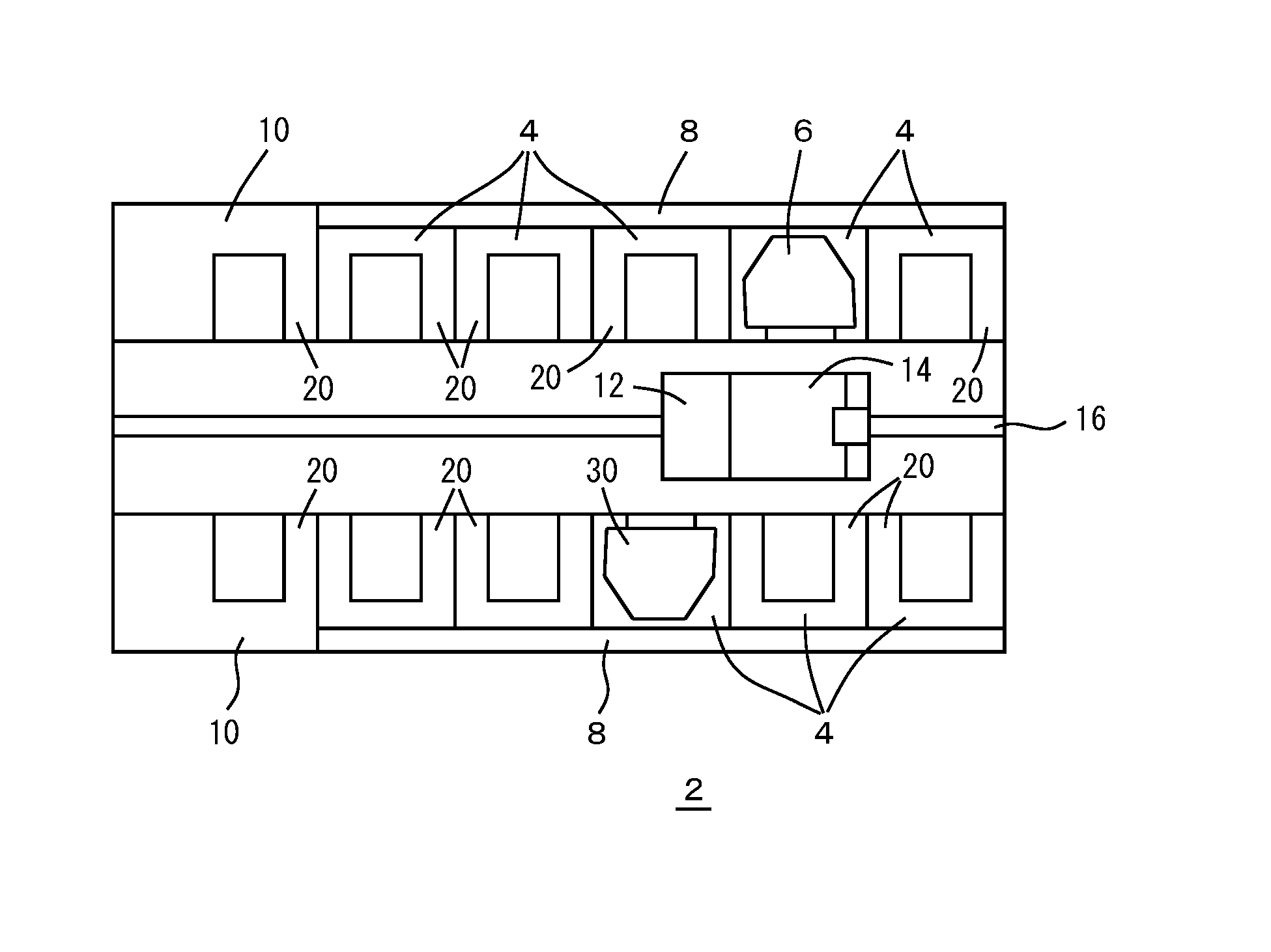
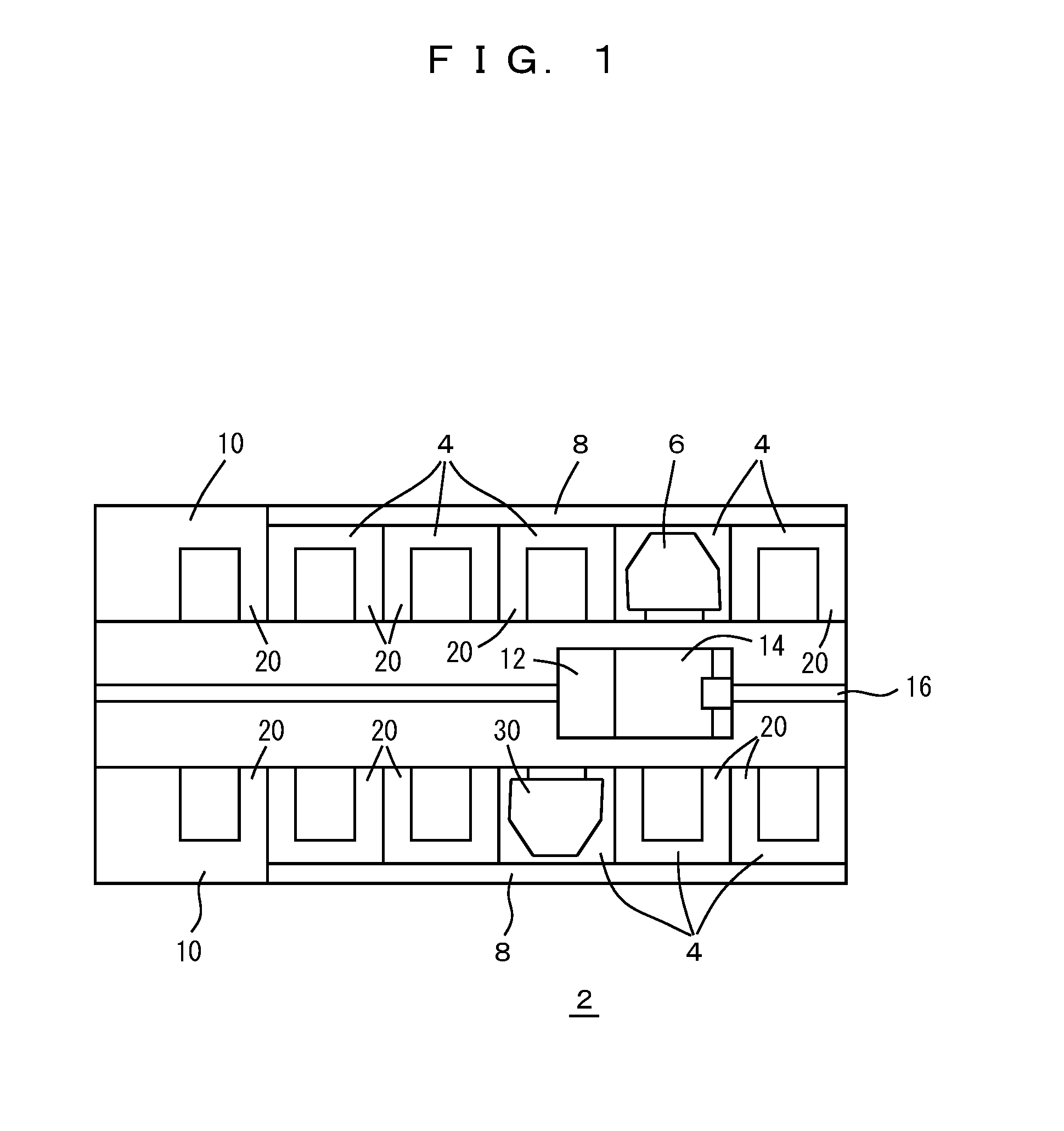
[0022]FIGS. 1 to 6 show a preferred embodiment and its modifications. FIG. 1 shows a stocker 2 that has an environment in which a measurement device 30 according to a preferred embodiment of the present invention is used. In the stocker 2, a plurality of cells 4 are provided and a carrier such as a FOUP 6 is stored in each cell 4. In the cell 4, a shelf support 20 on which the FOUP 6 is positioned and arranged is provided, and the purge gas such as a nitrogen gas or clean dry air is supplied from a purge gas supplying section 8 to pipes of the shelf support 20, and is supplied from the pipes to the FOUP 6 via nozzles 24 of FIG. 2. In the ...


PUM


Abstract

A purge gas flow rate in a carrier that houses a smaller number of articles than a usual number is measured. The flow rate of the purge gas supplied from a nozzle of a shelf support in a rack is measured by a measurement device. The measurement device includes a substrate, a gas introduction section provided on a bottom surface of the substrate and configured to introduce the purge gas when coming into contact with the nozzle of the shelf support, while maintaining contact with the nozzle airtight with a load from the substrate, a circuit including a flowmeter that measures the purge gas flow rate and a power supply, and a plurality of legs movable in a vertical direction with respect to the substrate and defining a portion of the weight of the measurement device supported on the shelf support.

Description

BACKGROUND OF THE INVENTION[0001]1. Field of the Invention[0002]The present invention relates to measurement of flow rate of a purge gas flowing into a carrier such as a FOUP in which semiconductor wafers or the like are housed.[0003]2. Description of the Related Art[0004]When articles such as semiconductor wafers or reticles are housed and stored in a carrier such as a FOUP or a reticle pod, a purge gas such as a nitrogen gas or clean dry air is supplied to the carrier in order to prevent contamination, oxidation, and the like of the wafers or the like. Specifically, the purge gas supply line is provided in a stocker, an automated warehouse, and the like in which the carrier is stored, and a nozzle of the supply line and a gas introduction section of the carrier are connected to each other so that the purge gas is introduced into the carrier. A valve of the gas introduction section is configured to open when the gas introduction section is set to the nozzle of the purge gas supply ...

Claims


Application Information

Patent Timeline
Patent Type & Authority Applications(United States)
IPC IPC(8): G01F1/56
CPCG01F1/56G01F1/28H01L21/67253H01L21/67769H01L21/67393
Inventor MURATA, MASANAOYAMAJI, TAKASHI
Owner MURATA MASCH LTD
Why Eureka
Try Eureka