Load inertia estimation method and control parameter adjustment method

a technology of load inertia and estimation method, which is applied in the direction of electric controllers, programme control, force/torque/work measurement apparatus, etc., can solve the problems of inability to compensate for position delay or vibration, and the addition of feed-forward control function to the feedback control system

Inactive Publication Date: 2013-09-12
MITSUBISHI HEAVY IND LTD
View PDF8 Cites 7 Cited by
  • Summary
  • Abstract
  • Description
  • Claims
  • Application Information

AI Technical Summary

Benefits of technology

[0022]The load inertia estimation method of the first aspect of the invention provides the method of estimating the load inertia of the feed system for the load position control system configured to cause the feedback control system, to which the inverse characteristic model of the feed system is added, to control the load position of the feed system on the basis of the amount of compensation outputted from the inverse characteristic model and used for compensating for the dynamic error factor of the feed system. Here, the method is characterized in that the method includes, in the load position control system, conducting a load position control test using the feedback control system by issuing a position command to the feedback control system, and measuring a position deviation between the position command and the load position arising at a prescribed load position at this time; and in a load inertia estimation model being a model of the load position control system, conducting load position control simulation on a model of the feed system using a model of the feedback control system by issuing the position command to the model of the feedback control system, repeating the load position control simulation while the load inertia included in the model of the feed system is adjusted until a position deviation between the position command and the load position arising at the prescribed load position in the load position control simulation becomes equal to the position deviation measured in the load position control test, and as a consequence, if the position deviation arising at the prescribed load position in the load position control simulation becomes equal to the position deviation measured in the load position control test, estimating the load inertia included in the model of the feed system at this time as the load inertia of the feed system. For this reason, even when the weight of a load on the feed system (such as the weight of a workpiece mounted on a table of a machine tool) varies, the load inertia corresponding to the load weight can easily be estimated.
[0023]The load inertia estimation method of the second aspect of the invention provides the method of estimating the load inertia of the feed system for the load position control system configured to cause the feedback control system, to which the inverse characteristic model of the feed system is added, to control the load position of the feed system on the basis of the amount of compensation outputted from the inverse characteristic model and used for compensating for the dynamic error factor of the feed system. Here, the method is characterized in that the method includes, in the load position control system, conducting a load position control test using the feedback control system by issuing a position command to the feedback control system and measuring a position deviation between the position command and the load position arising at a prescribed load position at this time, or in a model of the load position control system, conducting load position control simulation on a model of the feed system using a model of the feedback control system by issuing the position command to the model of the feedback control system and measuring the position deviation between the position command and the load position arising at the prescribed load position at this time; and finding load inertia corresponding to the position deviation measured in the load position control test or the load position control simulation on the basis of position deviation characteristic data which is preset based on the position deviation between the position command and the load position being measured in advance and arising at the prescribed load position when no load is applied and on the position deviation between the position command and the load position being measured in advance and arising at the prescribed load position when a certain load is applied and which increases linearly in proportion to an increase in the load inertia, and estimating the load inertia thus found as the load inertia of the feed system. For this reason, even when the load weight on the feed system (such as the weight of the workpiece mounted on the table of the machine tool) varies, the load inertia corresponding to the load weight can easily be estimated.
[0024]The control parameter adjustment method according to the third aspect of the invention provides the control parameter adjustment method of adjusting the load inertia included in the inverse characteristic model for the load position control system configured to cause the feedback control system, to which the inverse characteristic model of the feed system is added, to control the load position of the feed system on the basis of the amount of compensation outputted from the inverse characteristic model and used for compensating for the dynamic error factor of the feed system. Here, the method is characterized in that the method includes adjusting the load inertia included in the inverse characteristic model on the basis of the load inertia estimated by the load inertia estimation method according to the first or second aspect of the invention. Therefore, even when the load weight on the feed system (such as the weight of the workpiece mounted on the table of the machine tool) varies, it is possible to cause parameters of the feed system to match parameters of the inverse characteristic model (such as coefficients (to be described later in detail) in differential terms of third and higher orders including the term of the load inertia). For this reason, it is possible to perform precise control over the load position such that the load position follows the position command, and thereby to cause, for example, a machine tool to perform high-precision machining.

Problems solved by technology

However, it is difficult to achieve a sufficient following performance with the feedback control system 16 as in the illustrated example, and a delay of the load position θL in following the position command θ (namely, a delay in the load position) occurs as a consequence.
However, addition of the feed-forward control function to the feedback control system cannot compensate for a position delay or vibration caused by dynamic deformation such as deflection or torsion that occurs in a mechanical element in a controlled object.

Method used


Image

  • Load inertia estimation method and control parameter adjustment method
  • Load inertia estimation method and control parameter adjustment method
  • Load inertia estimation method and control parameter adjustment method

Examples


first embodiment

[0031](Description of Feedback Control System and Feed System)

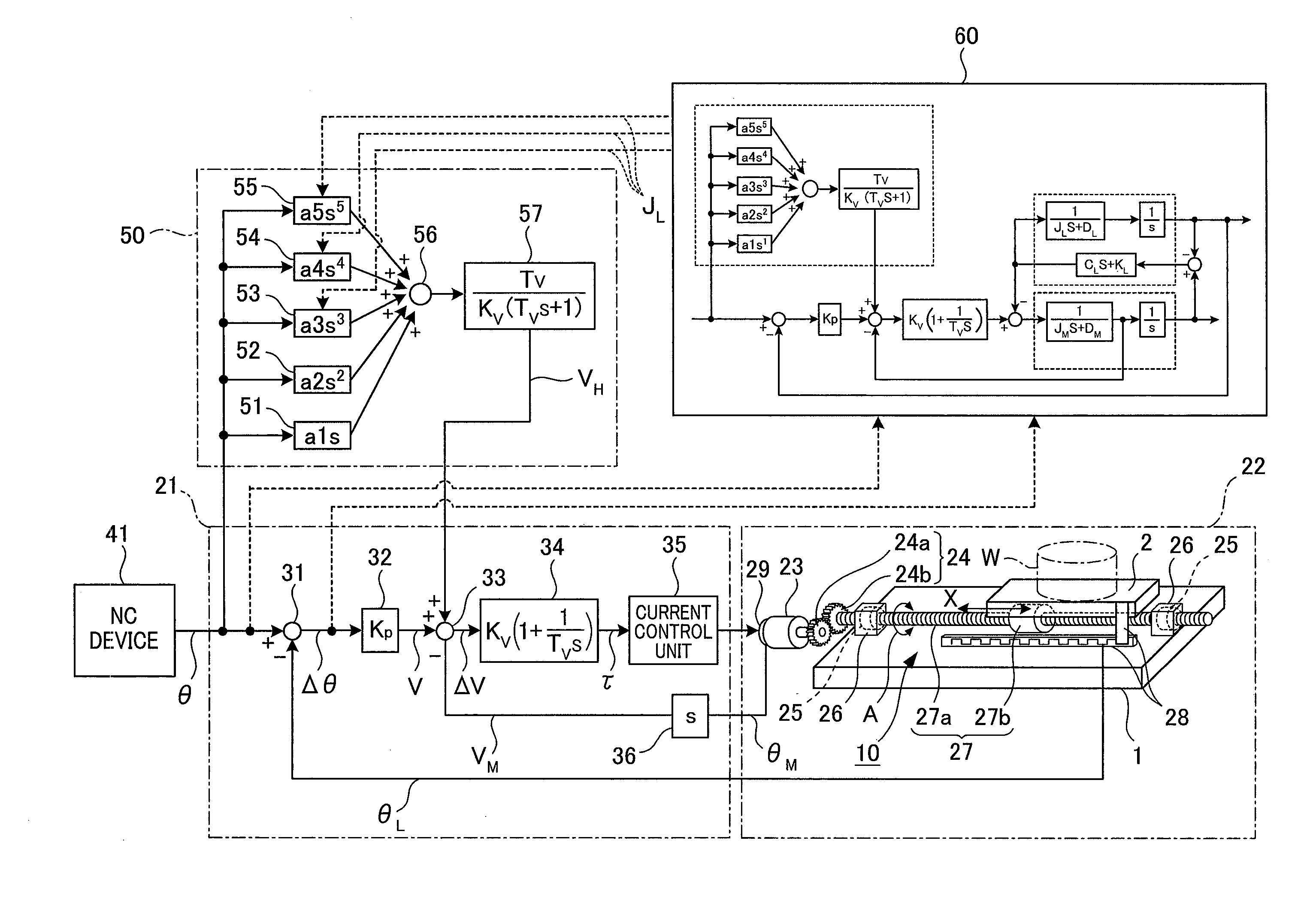
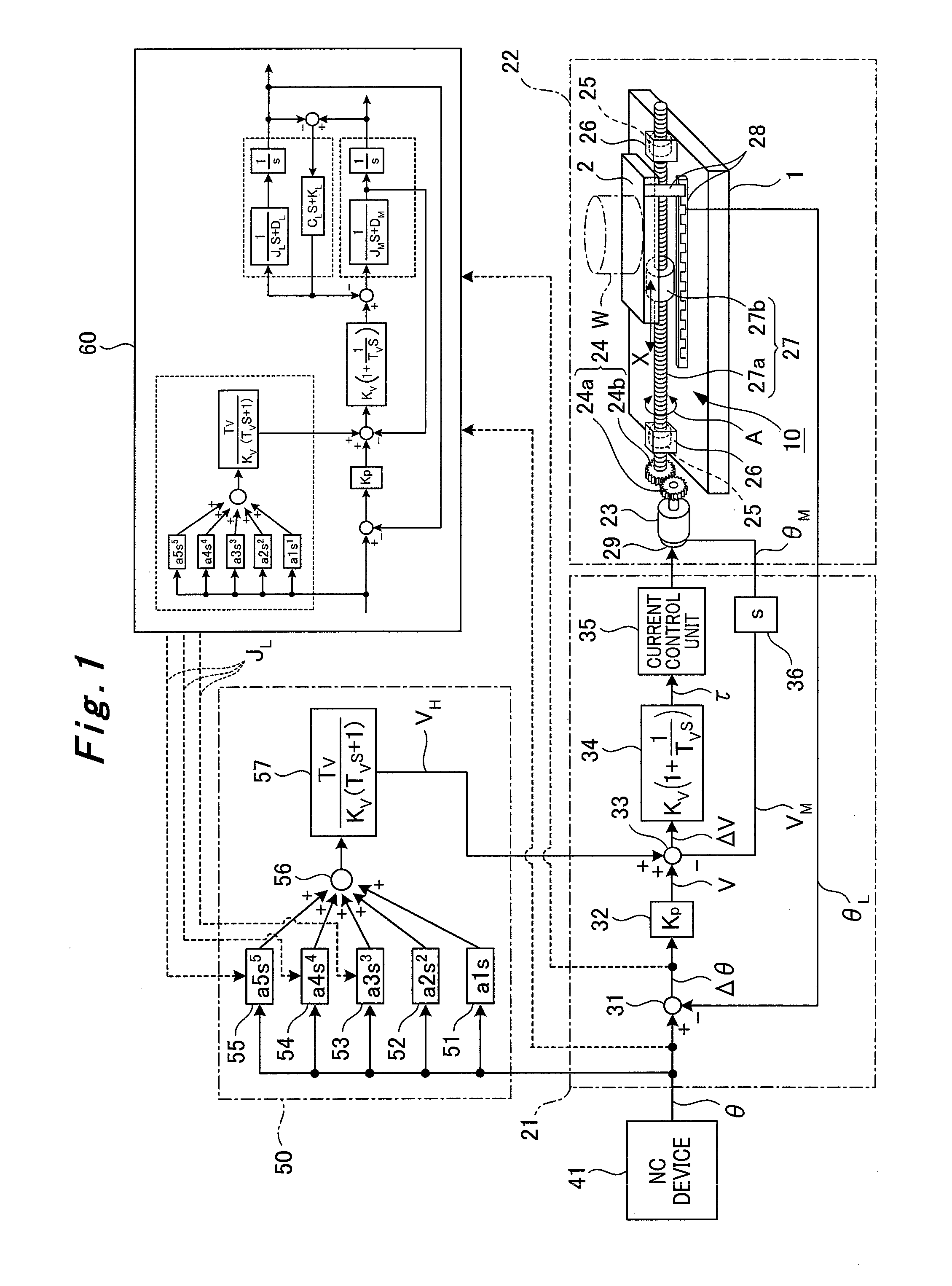
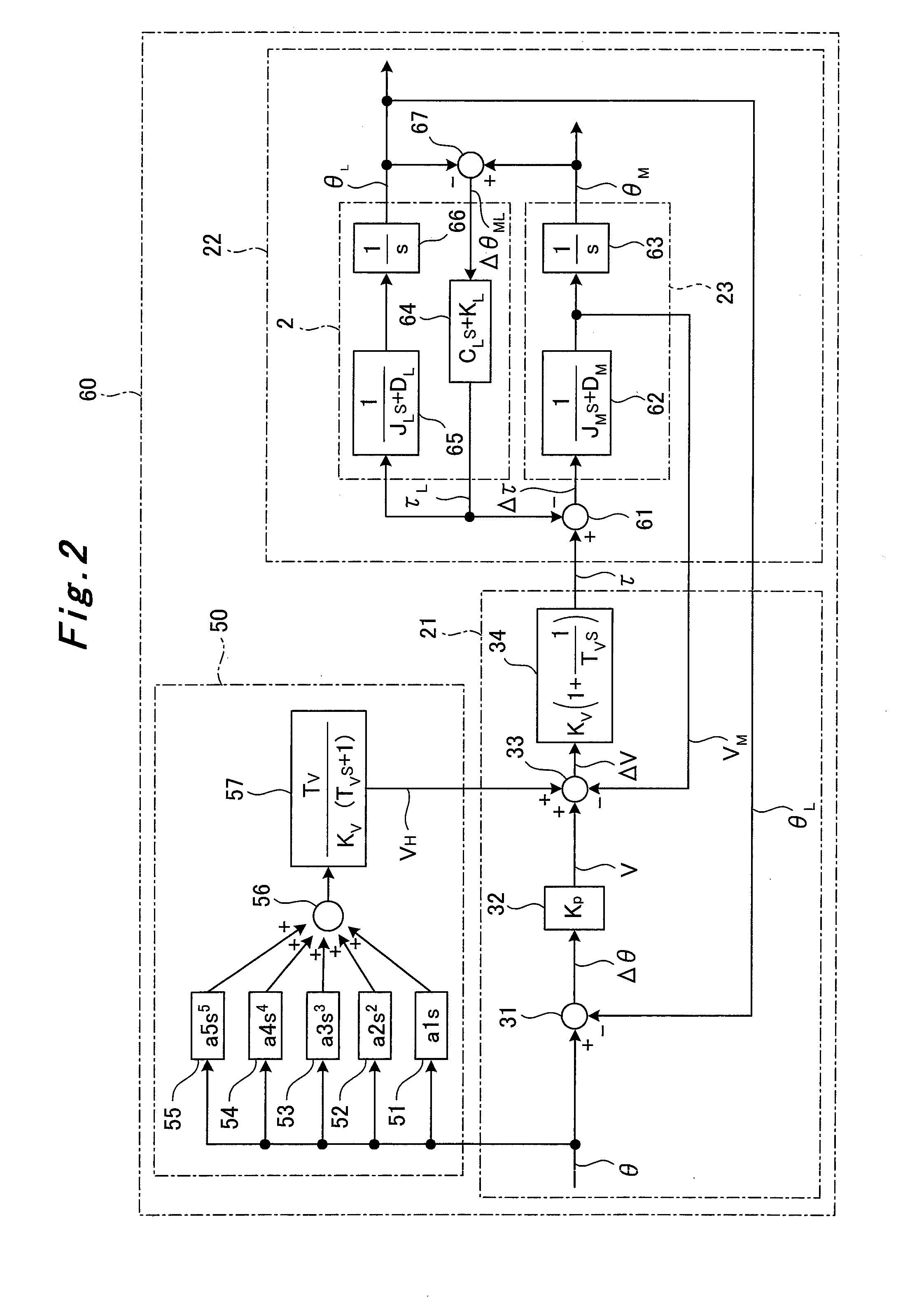
[0032]A configuration of a load position control system (a feedback control system 21 and a feed system 22) of a machine tool (see FIG. 4) which embodies a load inertia estimation method and a control parameter adjustment method according to an embodiment of the present invention will be described based on FIG. 1.

[0033]As shown in FIG. 1, the table feed system 22 includes a servo motor 23 being a drive source, a reduction gear unit 24 having a motor end gear 24a and a load end gear 24b, brackets 26 each incorporating a bearing 25, a ball screw 27 having a screw portion 27a and a nut portion 27b, a position detector 28, and a pulse encoder 29.

[0034]The brackets 26 on two sides are fixed to a bed 1 and rotatably support the screw portion 27a of the ball screw 27 via the bearings 25. The nut portion 27b of the ball screw 27 is attached to the table 2 and screwed to the screw portion 27a. The servo motor 23 is connected to th...

second embodiment

[0066](Description of Load Inertia Estimation Method and Control Parameter Adjustment Method)

[0067]A load inertia estimation method and a control parameter adjustment method according to a second embodiment of the present invention will be described based on FIG. 3. Note that portions in FIG. 3 similar to those in the first embodiment will be denoted by the same reference numerals and overlapping detailed description thereof will be omitted herein.

[0068]As shown in FIG. 3, a position deviation characteristic data unit 70 for estimating the load inertia JL corresponding to the weight of the workpiece W is added to the feedback control system 21 in the second embodiment.

[0069]A relational expression F=ma=KLΔθ (F: force, m: weight of workpiece, KL: spring rigidity of ball screw, Δθ: position deviation) holds between the position deviation Δθ (i.e., deflection of the ball screw 27 and the like) and the weight of the workpiece W. When the force F and the spring rigidity KL are made const...


PUM

PropertyMeasurementUnit
inertia estimationaaaaaaaaaa
load inertia estimation methodaaaaaaaaaa
load inertia estimationaaaaaaaaaa

Abstract

The purpose of the present invention is to provide a method for estimating load inertia and a method for adjusting control parameters. To achieve this aim, a load position control test is performed in a load position control system, based on a feedback control system (21) and a first position deviation (Δθ) generated at a prescribed load position (θL) is estimated. Then, in a load inertia estimation model (60) which is a model of a load position control system, a load position control simulation of a feed system model is performed based on a feedback control system model, a load inertia (JL) included in the feed system model is adjusted, and the load position control simulation repeated until a second position deviation (Δθ) that generated at this time at the prescribed load position equals the first position deviation. As a result, the load inertia for the feed system model at that time is estimated to be the load inertia for a feed system in an actual machine if the second position deviation equals the first position deviation. In addition, coefficients (a3-a5) for an inverse characteristic model (50) are set using this estimated load inertia.

Description

TECHNICAL FIELD[0001]The present invention relates to a load inertia estimation method and a control parameter adjustment method applicable to industrial machines such as machine tools.BACKGROUND ART[0002]Feedback control which is a classical control theory is generally used for load position control of a feed system in an industrial machine such as a machine tool.[0003]FIG. 4 shows an example of a machine tool. The machine tool of the illustrated example is a double column type machining center which includes a bed 1, a table 2, a gate-shaped column 3, a crossrail 4, a saddle 5, a ram 6, and a main spindle 7.[0004]The table 2 is disposed on the bed 1 and the column 33 is disposed in such a manner as to straddle the table 2. A workpiece W is mounted on the table 2 at the time of machining, and the table 2 moves linearly in an X-axis direction along guiderails 1a on the bed 1 with the assistance of a feed system (not shown in FIG. 4, see FIG. 5). The crossrail 4 moves linearly in a Z...

Claims


Application Information

Patent Timeline
Patent Type & Authority Applications(United States)
IPC IPC(8): G01L5/00G05B11/01G05B13/04
CPCG05B19/404G05B2219/41381G05B11/01G01L5/00G05B2219/41123G05B13/04
Inventor KURAMOTO, HIROHISAYAMADA, YASUNARI
Owner MITSUBISHI HEAVY IND LTD
Why Eureka
Try Eureka