Near-infrared lens for cameras in mobile devices

a technology of infrared and mobile devices, applied in the field of optical imaging lens systems, can solve the problems that the optical imaging lens system's size reduction must also take into account optical performance requirements

Active Publication Date: 2015-12-24
GENIUS ELECTRONICS OPTICAL CO LTD
View PDF1 Cites 59 Cited by
  • Summary
  • Abstract
  • Description
  • Claims
  • Application Information

AI Technical Summary

Problems solved by technology

However, the size reduction of the optical imaging lens systems also has to take into account optical performance requirements.

Method used


Image

  • Near-infrared lens for cameras in mobile devices
  • Near-infrared lens for cameras in mobile devices
  • Near-infrared lens for cameras in mobile devices

Examples


first embodiment

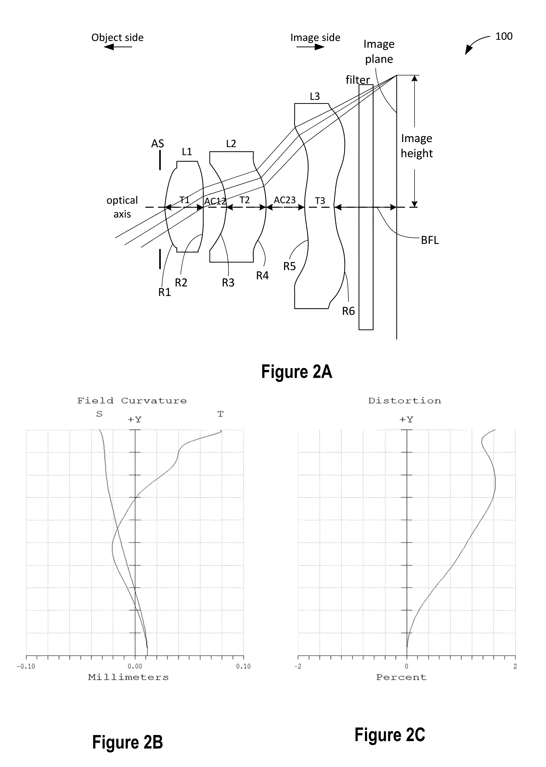
[0052]FIG. 2A is a simplified cross-section view of a three-element optical lens system 100 according to a first embodiment of the present invention. Optical lens system 100 comprises a first lens element L1, a second lens element L2, and a third lens element L3, in order from the object side to the image side along the optical axis. Each lens element L1-L3 can be rotationally symmetric above the optical axis.

[0053]First lens element L1 has a positive refractive power, a convex object-side surface, a convex image-side surface in the outer circumferential region, and a convex image-side surface in the vicinity of the optical axis. Second lens element L2 has a negative refractive power, a concave object-side surface in the vicinity of the optical axis, a concave object-side surface in the outer circumferential region, a convex image-side surface in the vicinity of the optical axis, and a convex image-side surface in the outer circumferential region. Third lens element L3 has a positiv...

second embodiment

[0066]Table 2A shows numeric lens data of the lens elements of optical lens system 100 according to a second embodiment of the present invention. All three lens elements are made of the polycarbonate plastic material SP3810.

TABLE 2ACurvatureRadiusRadiusThickness / air gapRefractive(1 / mm)(mm)(mm)indexAbbe #materialObjectInfinity14400Aperture stopInfinity−0.1275Lens 18.40E−011.1904290.511.63975323.35202SP38108.69E−0211.504110.25357Lens 2−7.97E−01 −1.254710.5246341.63975323.35202SP3810−6.66E−01 −1.502170.572298Lens 37.85E−011.2741210.351.63975323.35202SP38101.16E+000.8592370.36filterInfinity0.211.5264.2Infinity0.3Image planeInfinity0

[0067]In the second embodiment, the effective focal length (EFL) is 2.5631 mm, the half field of view (HFOV) is 36.1 degrees. The F number is 2.19. The image height is 1.87 mm. The BFL is 0.87 mm. The entire length of the optical system 100 measured from the object-side surface of the first lens element to the image plane is 3.081 mm. The angular magnificatio...

third embodiment

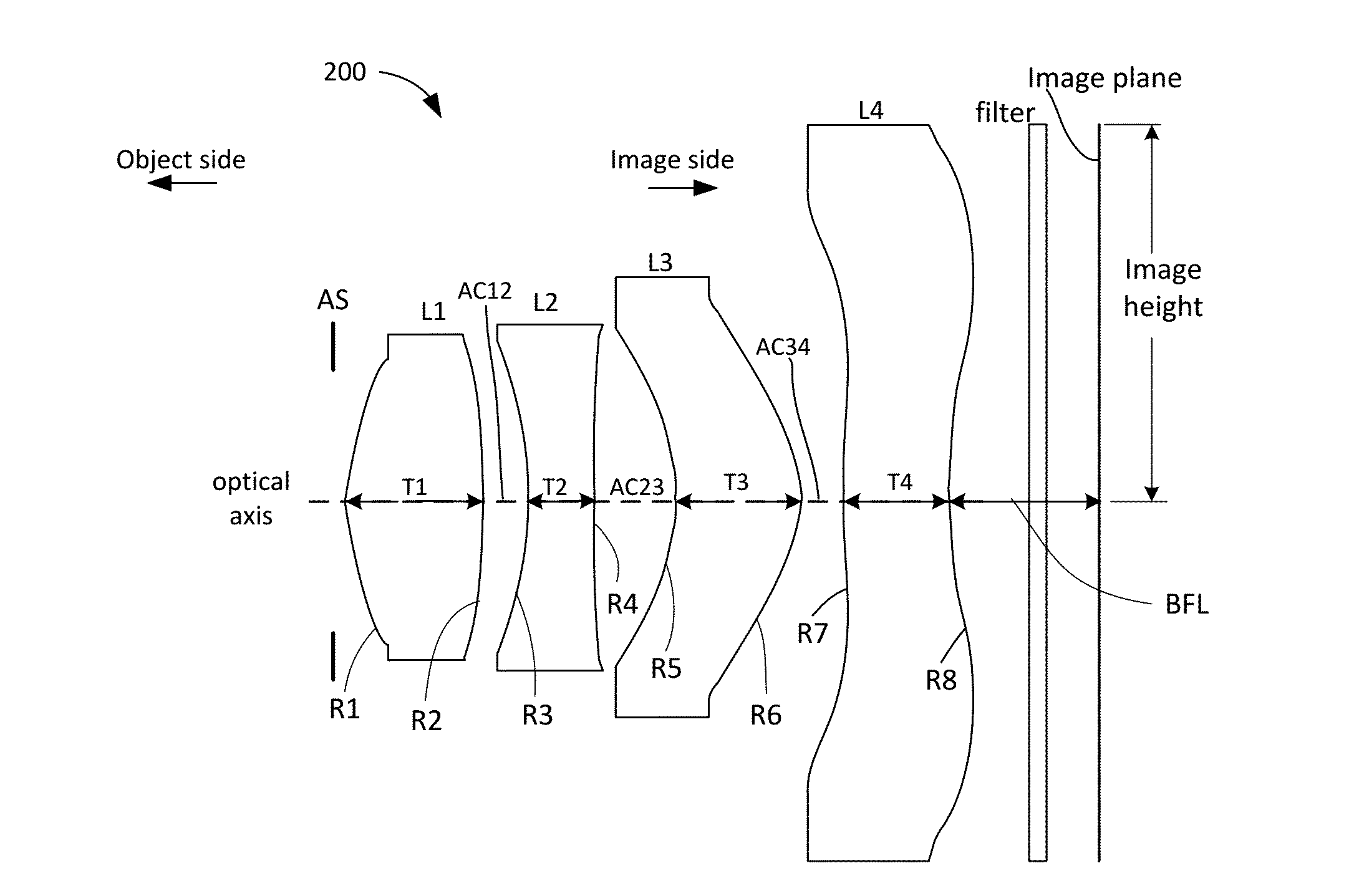
[0071]FIG. 3A is a simplified cross sectional view of a four-element optical lens system 200 according to an embodiment of the present invention. Optical lens system 200 includes an aperture stop AS, a first lens element L1, a second lens element L2, a third lens element L3, and a fourth lens element L4, in order from the object side to the image side along the optical axis. Each lens element L1-L4 can be rotationally symmetric above the optical axis.

[0072]First lens element L1 has a positive refractive power, a convex object-side surface, a convex image-side surface in the outer circumferential region, and a concave image-side surface in the vicinity of the optical axis. Second lens element L2 has a negative refractive power, a concave object-side surface in the vicinity of the optical axis, a concave object-side surface in the outer circumferential region, a concave image-side surface in the outer circumferential region, and a concave image side surface in the vicinity of the opti...


PUM


Abstract

A first optical imaging system includes, in order from the object side to the image side, a first lens element, a second lens element, and a third lens element, arranged along an optical axis. A second optical imaging system includes, in order from the object side to the image side, a first lens element, a second lens element, a third lens element, and a fourth lens element, arranged along an optical axis. A third optical imaging system is a telecentric lens system having only lens elements having a refractive power and a chief ray angle smaller than 1 degree. The lens elements of the optical imaging systems may be made of the same material having absorption in visible wavelengths and high transmission in near infrared radiation. The lens elements may be coated with an antireflective coating that is optimized for near infrared radiation.

Description

CROSS-REFERENCES TO RELATED APPLICATIONS[0001]This application claims the benefit of U.S. Provisional Patent Application No. 62 / 015,867, filed Jun. 23, 2014, U.S. Provisional Patent Application No. 62 / 052,181, filed Sep. 18, 2014, and U.S. Provisional Patent Application No. 62 / 061,516, filed Oct. 8, 2014, the contents of which are hereby incorporated by reference in their entirety.BACKGROUND OF THE INVENTION[0002]The present disclosure relates to optical lens systems, and more particularly to near infrared optical imaging lens systems having three lens elements and four lens elements for cameras incorporated in mobile electronic devices.[0003]Mobile electronic devices with built-in digital cameras are becoming increasingly popular. Along with trends of downsizing in digital cameras and cell phones and recent technological advances in charge coupled devices (CCD) and CMOS imaging sensors, optical lens systems also need to reduce their size. However, the size reduction of the optical ...

Claims


Application Information

Patent Timeline
Patent Type & Authority Applications(United States)
IPC IPC(8): G02B13/00H04N5/225G02B9/34H04N5/33
CPCG02B13/004G02B9/34H04N5/2254H04N5/33G02B13/0035G02B13/14
Inventor BONE, MATTHEW
Owner GENIUS ELECTRONICS OPTICAL CO LTD
Why Eureka
Try Eureka