

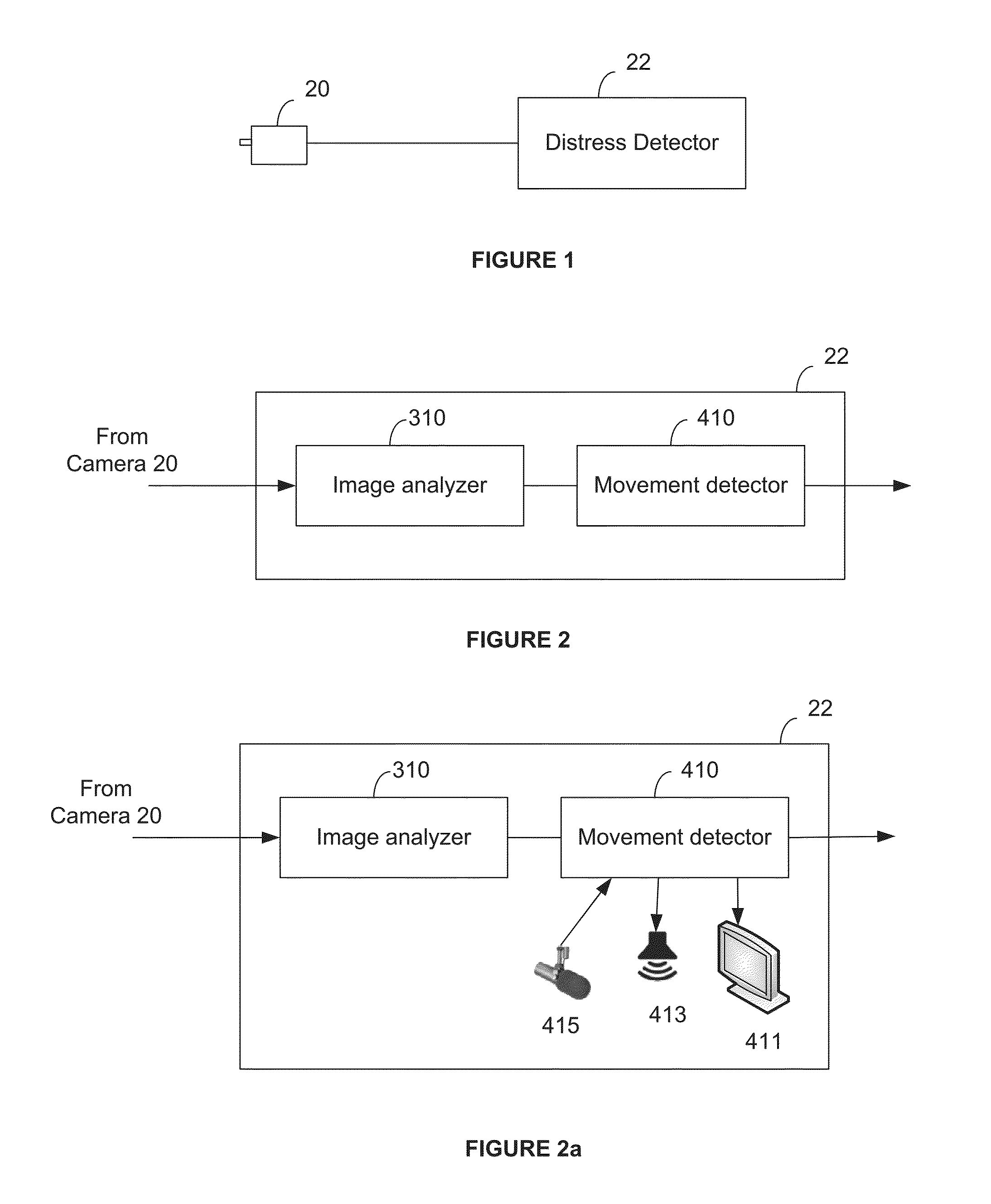
Vision based system for detecting distress behavior
a vision based system and distress behavior technology, applied in the field of vision based systems for detecting distress behavior, can solve the problems of system impracticality, privacy and accuracy, and the cost of hiring a person who is performing the hiring
- Summary
- Abstract
- Description
- Claims
- Application Information
AI Technical Summary
Benefits of technology
Problems solved by technology
Method used
Image

Examples
embodiment using 2d
Images
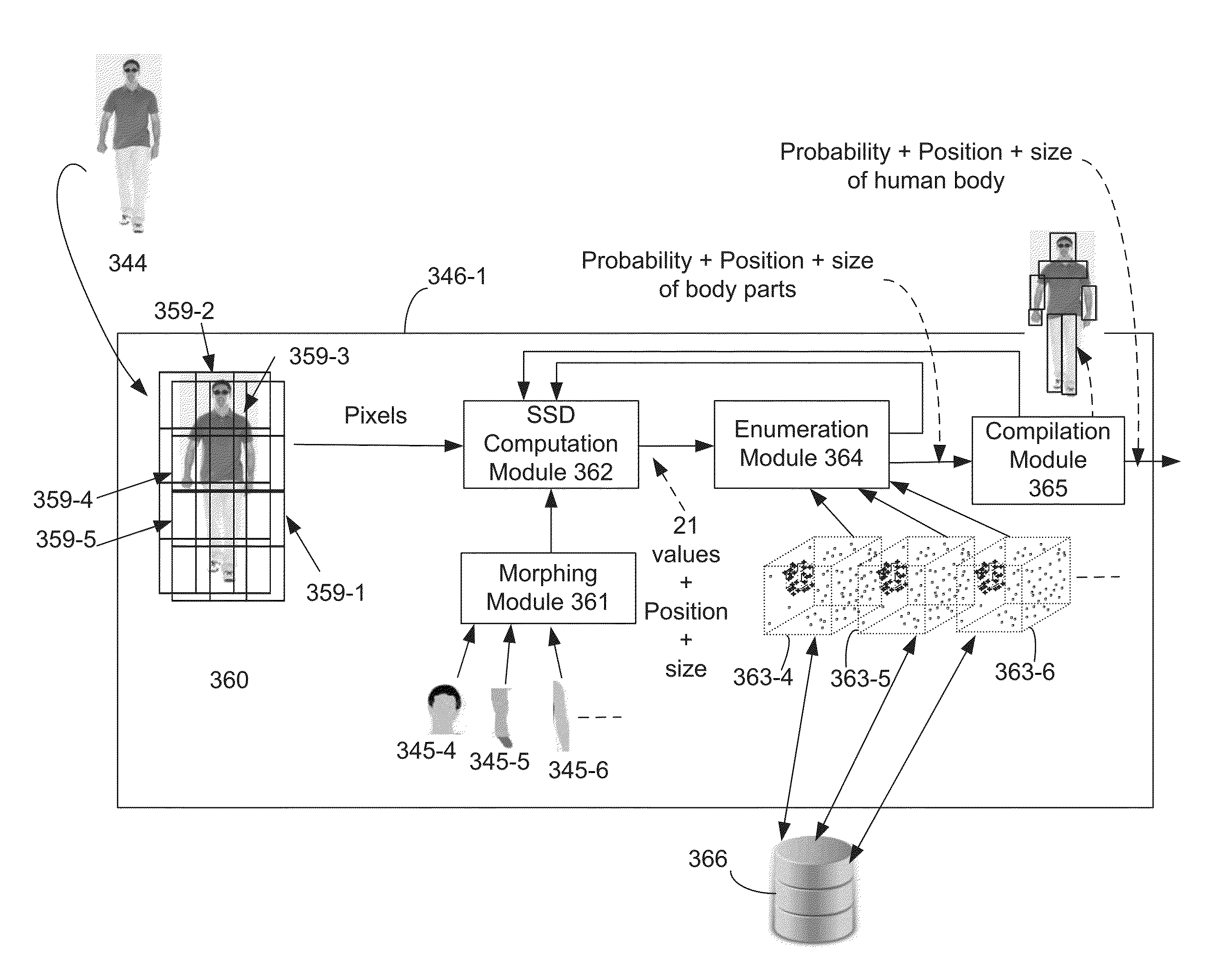
[0097]The first embodiment uses a 2D image set. Tracking may be done as a post processing once confidence, size, and position, are reported to a kinematics / movement analyzer. In the present embodiment, it is possible to use the following fk function to go from N->P. It must be noted that the apparatus operates on a subset of N because the images are coded with pixels with 8 or 16 bits of significance, so that sub-image of N pixels are member of N.
[0098]In an embodiment, the chosen function fk may be expressed using the following function:
fk=fSSDοfconvοftile
where ftile fconv and fSSD are as follows:
[0099]1) Ftile
[0100]Ftile is the transformation function from N->P×M. P being the goal number, here taken from the value computed for a number of tiles (21) as explains below. M being an arbitrary number that depends upon the submitted images e.g. M may be the number that allows accounting for the number of pixels that is necessary to make one of the P tiles. In an embodiment, P*M>...
PUM
 Abstract
Description
Claims
Application Information