Dual band antenna device

a dual-band antenna and antenna technology, applied in the direction of resonant antennas, polarised antenna unit combinations, particular array feeding systems, etc., can solve the problems of reducing the radiation efficiency of the antenna and the deterioration of the signal by the increase of the correlation coefficient, so as to prevent the reduction of the frequency bandwidth

Inactive Publication Date: 2015-12-24
NEC CORP
View PDF3 Cites 16 Cited by
  • Summary
  • Abstract
  • Description
  • Claims
  • Application Information

AI Technical Summary

Benefits of technology

[0010]By using the present invention, the frequency bandwidth can be prevented from being reduced by using a predetermined coupling element and a frequency adjustment element.

Problems solved by technology

However, when a plurality of antenna units with the same resonant frequency are closely arranged in the portable communication terminal having a small mounting area, an electromagnetic coupling occurs between the antenna units and whereby, an antenna radiation efficiency is reduced and a signal is deteriorated by the increase of the correlation coefficient.

Method used


Image

  • Dual band antenna device
  • Dual band antenna device
  • Dual band antenna device

Examples


first exemplary embodiment

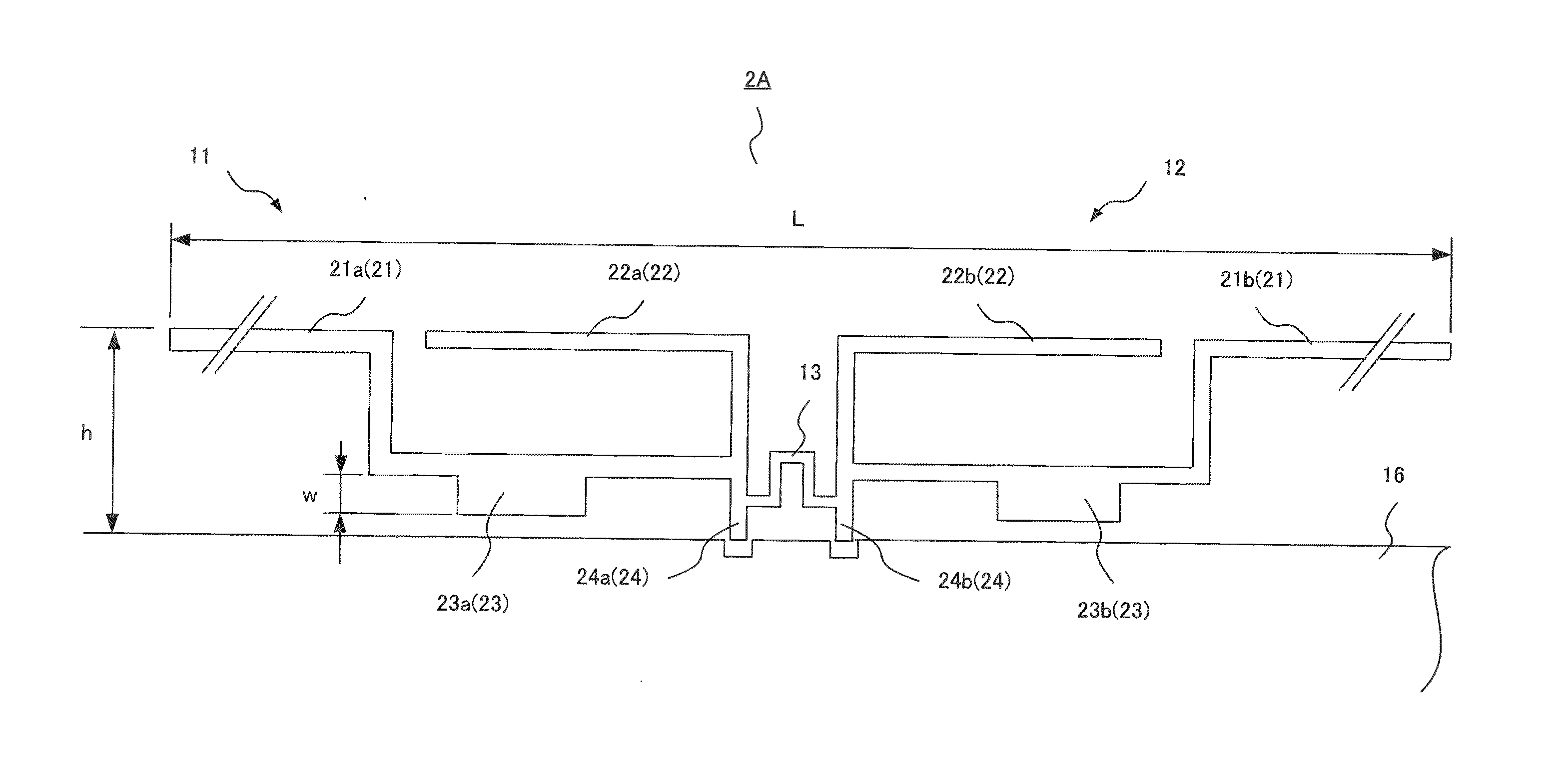
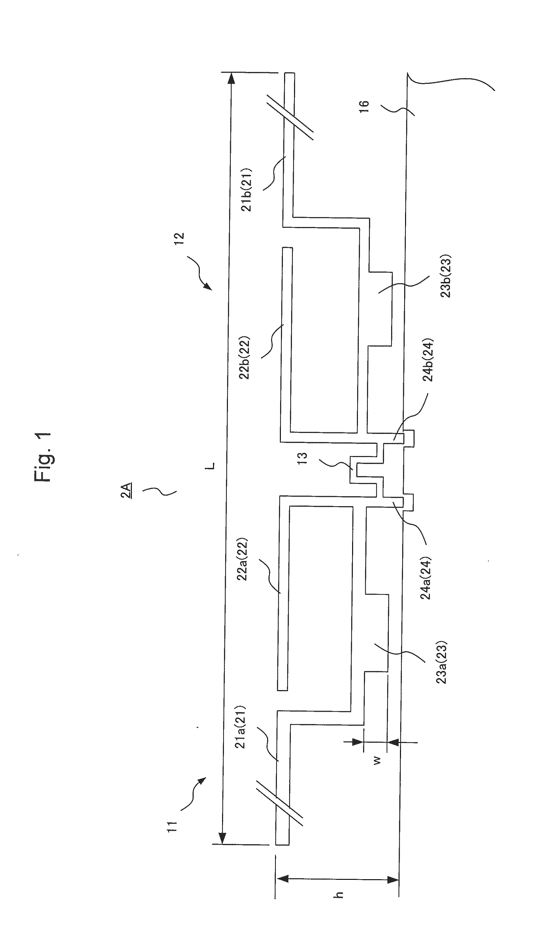
[0027]Next, a first exemplary embodiment of the present invention will be described. FIG. 1 is a figure showing a structure of an antenna device 2A according to the first exemplary embodiment. The antenna device 2A is composed of a first antenna unit 11, a second antenna unit 12, and a coupling element 13 which couples these units to each other as basic elements.

[0028]This first antenna unit 11 includes a first long element 21a (21), a first short element 22a (22), a first frequency adjustment element 23a (23), and a first power feeding port 24a (24). Further, the second antenna unit 12 includes a second long element 21b (21), a second short element 22b (22), a second frequency adjustment element 23b (23), and a second power feeding port 24b (24). Here, the word of “long” of the long element 21 (21a and 22a) means that the long element 21 has a branch structure in which a length of the branch is greater than that of the short element 22 (22a and 22b). Namely, the length of the long ...

second exemplary embodiment

[0051]Next, a second exemplary embodiment of the present invention will be described. Further, the same reference numbers are used for the elements having the same function as the first exemplary embodiment and the description will be omitted appropriately.

[0052]FIG. 9 a figure showing a structure of an antenna device 2B according to this exemplary embodiment. The basic structure of the antenna device 2B is the same as that of the antenna device 2A. However, in the antenna device 2B, the first antenna unit 11 and the second antenna unit 12 are arranged so as to be perpendicular to each other and these units are arranged at a corner of the ground plate 16.

[0053]The first power feeding port 24a and the second power feeding port 24b are connected to each other at a position in the vicinity of the corner point of the ground plate 16. The coupling element 13 is laid along the corner and connects the first antenna unit 11 and the second antenna unit 12.

[0054]Because a current mode of the ...

third exemplary embodiment

[0058]Next, a third exemplary embodiment of the present invention will be described. Further, the same reference numbers are used for the elements having the same function as the first exemplary embodiment and the description will be omitted appropriately.

[0059]The size of the antenna device according to this exemplary embodiment is further reduced compared to the antenna device described above. Namely, in the second exemplary embodiment, the antenna device is arranged at the corner of the ground plate. As a result, the longitudinal length of the antenna device is substantially reduced. In contrast, in this exemplary embodiment, the long element of the antenna device has a meander structure in which the element is formed in a meander shape. As a result, the size of the antenna device is reduced.

[0060]FIG. 12 is a figure showing a structure of an antenna device 2C according to this exemplary embodiment. As shown in FIG. 12, the first antenna unit 11 and the second antenna unit 12 of ...


PUM


Abstract

A dual band antenna device includes a first antenna unit which includes a first long element, a first short element whose resonant frequency is different from the resonant frequency of the first long element, a first frequency adjustment element provided in the first long element to adjust the resonant frequency, and a first power feeding port that is a power feeding end; a second antenna unit which includes a second long element, a second short element whose resonant frequency is different from the resonant frequency of the second long element, a second frequency adjustment element provided in the second long element to adjust the resonant frequency, and a second power feeding port that is a power feeding end; and a coupling element which connects the first antenna unit and the second antenna unit while adjusting a mutual impedance between the first antenna unit and a second antenna unit.

Description

TECHNICAL FIELD[0001]The present invention relates to a dual band antenna device which transmits and receives an electric wave in a plurality of frequency bands.BACKGROUND ART[0002]In recent years, a MIMO (Multiple-Input Multiple-Output) system is widely used and for this reason a wireless communication device such as a portable communication terminal begins to use an antenna device including a plurality of antenna units with the same resonant frequency. In this MIMO system, a spatial multiplexing transmission in which different information streams are transmitted by a plurality of antennas of a transmission side and received by a plurality of antennas of a reception side is adopted and whereby, a transmission capacity is increased.[0003]However, when a plurality of antenna units with the same resonant frequency are closely arranged in the portable communication terminal having a small mounting area, an electromagnetic coupling occurs between the antenna units and whereby, an antenn...

Claims


Application Information

Patent Timeline
Patent Type & Authority Applications(United States)
IPC IPC(8): H01Q5/335H01Q21/00H01Q5/10H01Q1/50
CPCH01Q1/2291H01Q1/521H01Q9/42H01Q5/10H01Q5/335H01Q1/50H01Q21/0006H01Q21/205H01Q21/24H01Q5/371
Inventor YOSHIDA, TAKAHIDE
Owner NEC CORP
Why Eureka
Try Eureka