Electric heating device

a heating device and heating element technology, applied in the direction of heater elements, air heaters, light and heating apparatus, etc., to achieve the effect of improving the positioning of sealing elements, ensuring elasticity, and optimizing the positive locking connection

Active Publication Date: 2015-12-24
MAHLE INT GMBH
View PDF1 Cites 1 Cited by
  • Summary
  • Abstract
  • Description
  • Claims
  • Application Information

AI Technical Summary

Benefits of technology

[0017]The bevel can be a surface formation at a sloping surface and / or edge of the inner edge surface of the housing cover and / or housing base in the area of the opening. The bevel in this case can have an angle of approximately 30° to 70°, preferably 45°, to the plane, facing the opening, of the housing cover and / or housing base. The inner edge surface can extend substantially perpendicular to the extension direction of the housing cover. The sealing element can have a certain elasticity and be compressible. A so-called press fit can result thereby during assembly. It can be made possible hereby that a lower exertion of force is necessary to dispose, particularly to fit, the sealing element optimally in the opening in the housing cover and / or housing base. As a result, the heating element can be accommodated optimally in the opening and be disposed securely therein. Apart from realizing the tight connection, the bevel can also improve the positioning of the sealing element in the housing cover and / or housing base.
[0018]In an embodiment of the electric heating device, a silicone adhesive and / or silicone gel and / or liquid silicone can be placed at a connecting line between the heating element and the housing cover and / or the housing base in the area of the opening. In this regard, the silicone adhesive and / or the silicone gel can have the function of the sealing element. The positive-locking connection can be optimized as a result. The sealing function between the sealing element and the housing cover and / or housing base can be stable and tight overall against dust, dirt, and moisture.

Problems solved by technology

In this regard, the electric auxiliary heating is used after the internal combustion engine has been started, as long as the internal combustion engine still cannot provide sufficient thermal energy.

Method used


Image

  • Electric heating device
  • Electric heating device
  • Electric heating device

Examples


Embodiment Construction

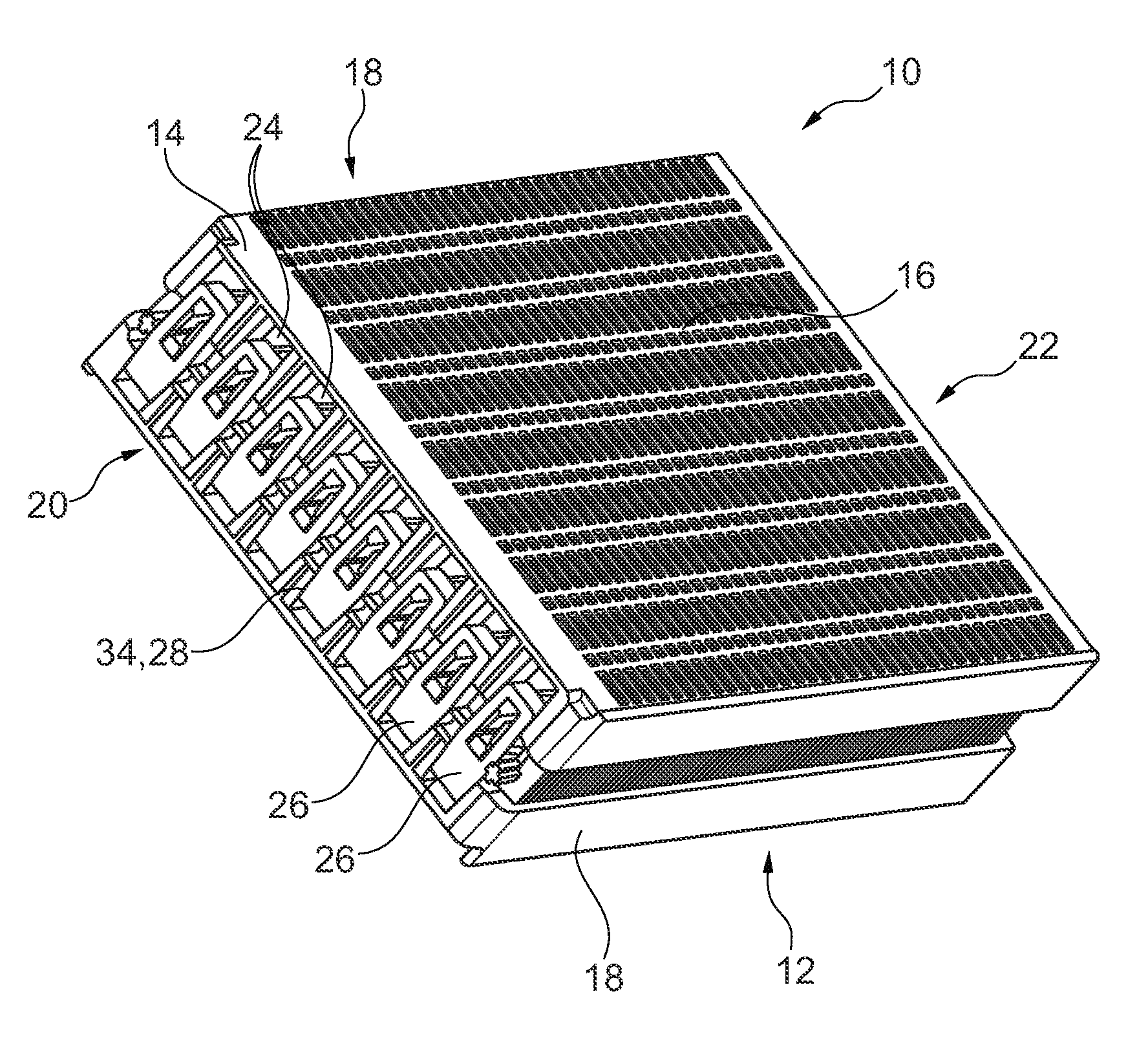
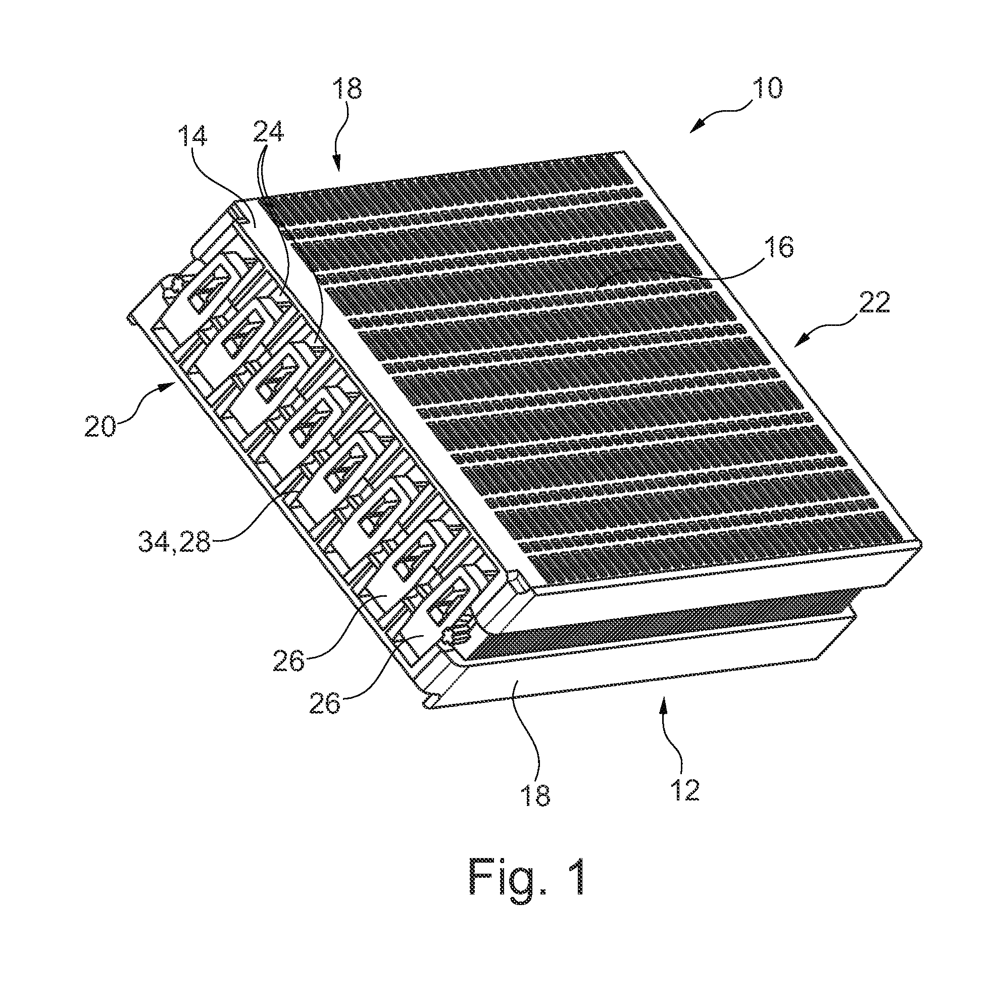
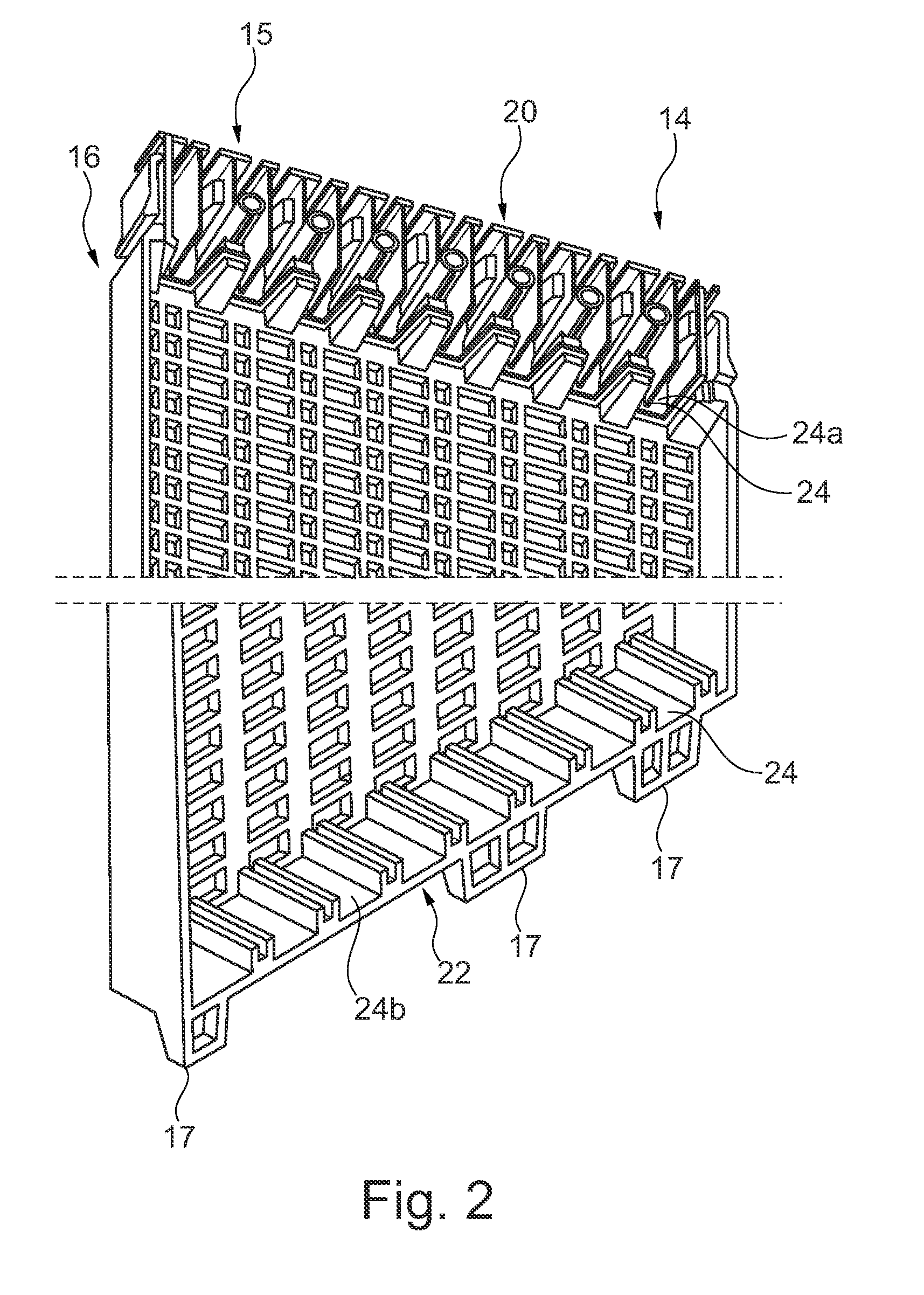
[0044]FIG. 1 shows an electric heating device 10, which has a housing 12, in a perspective view. Housing 12 in a first embodiment has a plastic frame 14. Plastic frame 14 is used for receiving heating elements (not shown) which can have PTC heating elements. Housing 12 has two housing side elements 16, two housing front elements 18, a housing cover 20, and a housing base 22. Openings 24 in which a heating element (not shown) with a sealing element 26 can be disposed are provided in each case in housing cover 20 and / or in housing base 22. In this case, the heating element is placed in each case in sealing element 26 and / or supported thereby. Sealing element 26 is preferably a flexible sealing element 26 and can represent a molded seal made of an elastic material, especially an elastic plastic. Alternatively, sealing element 26 can be configured as an adhesive / spring combination. Fabrication tolerances of openings 24 in housing cover 20 and / or housing base 22 can be compensated in thi...


PUM

PropertyMeasurementUnit
angleaaaaaaaaaa
angleaaaaaaaaaa
voltageaaaaaaaaaa

Abstract

An electric heating device, particularly for a motor vehicle, is provided that has at least one heating element disposed in a housing, whereby the housing has a housing cover and/or a housing base with at least one opening through which the at least one heating element is disposed protruding at least in sections, whereby a sealing element in which the at least one heating element is disposed is provided in the at least one opening in the housing cover and/or in the housing base.

Description

[0001]This nonprovisional application claims priority under 35 U.S.C. §119(a) to European Patent Application No. EP 14173063.0, which was filed on Jun. 18, 2014, and which is herein incorporated by reference.BACKGROUND OF THE INVENTION[0002]1. Field of the Invention[0003]The present invention relates to an electric heating device, particularly for a motor vehicle, and to a method for producing the electric heating device. The invention relates in addition to a motor vehicle having the electric heating device.[0004]2. Description of the Background Art[0005]Electric heating devices are known from the conventional art and are also used as electric auxiliary heaters in a motor vehicle. In particular in motor vehicles with a consumption-optimized internal combustion engine and / or in an electric vehicle, electric heating devices are used to heat a passenger compartment of the motor vehicle and / or of the engine. In this regard, the electric auxiliary heating is used after the internal comb...

Claims


Application Information

Patent Timeline
Patent Type & Authority Applications(United States)
IPC IPC(8): H05B3/26B60H1/22
CPCY10T29/49004B60H1/2215B60H2001/2278H05B3/267F24H3/0405F24H9/1872F24H3/0435F24H3/0441F24H3/0447F24H3/0464F24H9/1863F24H3/0429
Inventor ZIRGEL, THOMAS
Owner MAHLE INT GMBH
Why Eureka
Try Eureka