Eureka AIR delivers breakthrough ideas for toughest innovation challenges, trusted by R&D personnel around the world.

Pixelated Projection for Automotive Headlamp

Active Publication Date: 2015-12-31
TEXAS INSTR INC
View PDF10 Cites 65 Cited by
  • Summary
  • Abstract
  • Description
  • Claims
  • Application Information

AI Technical Summary

Benefits of technology

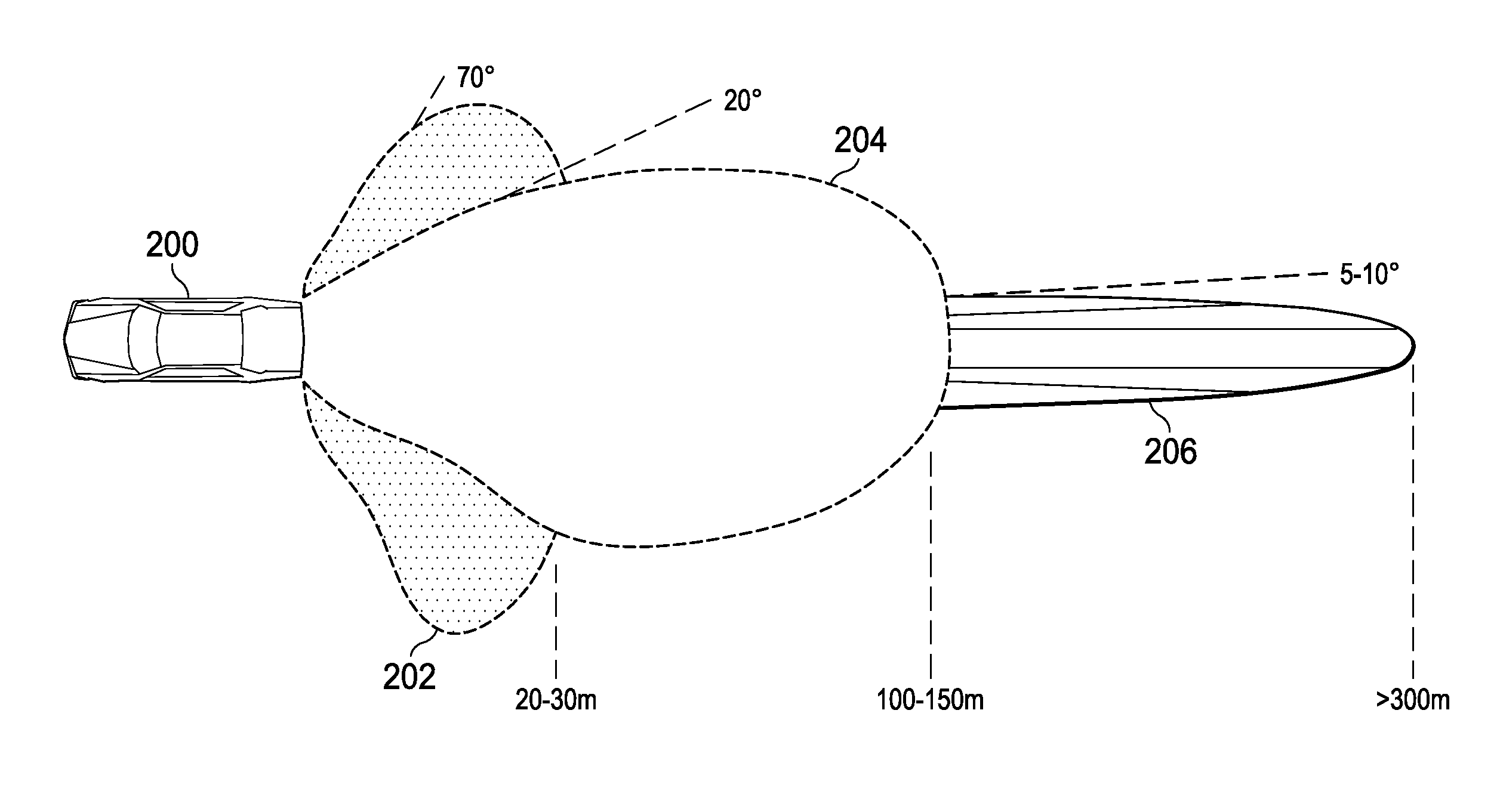
The present disclosure describes a method and apparatus for a pixelated projection in an automotive headlamp. This involves using a digital micromirror device (DMD) headlight module which includes a DMD and a white light module to provide a white light beam to illuminate the DMD. The white light beam is then prepped by illumination optics and sent to the DMD for pixelated projection. The DMD, white light module, and illumination optics work together to create a pixelated non-uniform beam profile, which is ideal for projecting a white light beam that forms a portion of the headlamps' white light beam. The headlamp's white light beam includes low beam light, mid-beam light, and high beam light portions. This technology allows for precise beam shaping and improved visibility for drivers.

Problems solved by technology

Limited resolution can cause stark changes to the light output as a masked object moves across the headlight field of view.
In addition, as one LED is turned off and another turned on, the change may be noticeable and even distracting to the driver of the equipped vehicle as well as to oncoming drivers.

Method used


Image

  • Pixelated Projection for Automotive Headlamp
  • Pixelated Projection for Automotive Headlamp
  • Pixelated Projection for Automotive Headlamp

Examples


Embodiment Construction

[0017]Specific embodiments of the disclosure will now be described in detail with reference to the accompanying figures. Like elements in the various figures are denoted by like reference numerals for consistency.

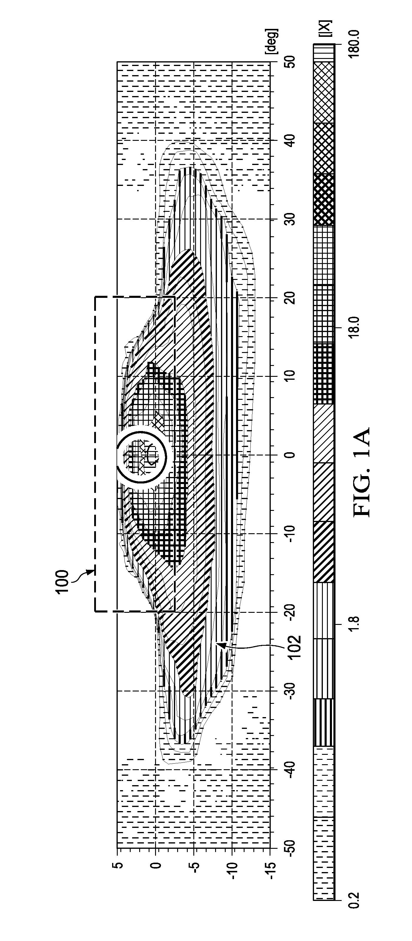
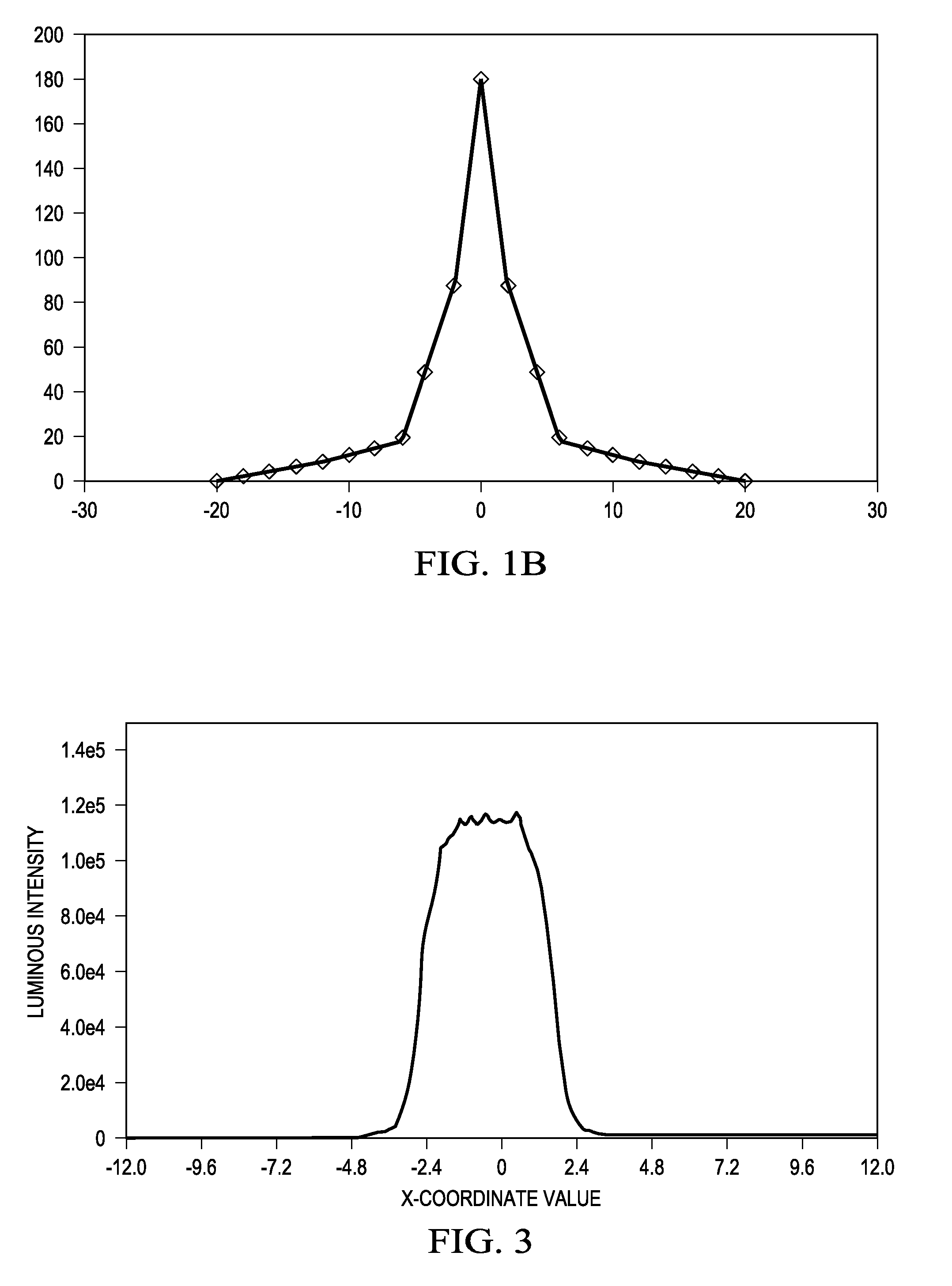
[0018]FIGS. 1A and 1B are graphs illustrating the beam profile of a typical high beam with both headlamps of a vehicle are in high beam mode. Referring first to FIG. 1A, the distribution 100 of the high beam in the field of view (FOV) is approximately between −20 degrees and 20 degrees. The distribution 102 of the low beam in the FOV is much broader, approximately between −40 degrees and 40 degrees. The circle indicates the spot within the high beam where peak intensity is highest. This is where a headlamp needs the highest intensity so the driver can see as far as possible down the road. FIG. 1B is a plot of the one dimensional distribution of the light in the high beam profile 100. As can be seen from this plot, the high beam has very high intensity in the center and the ...


PUM


Abstract

An automotive headlamp is provided that includes a digital micromirror device (DMD) headlight module, the DMD headlight module including a DMD, a white light module to provide a white light beam to illuminate the DMD, illumination optics optically coupled between the DMD and the white light module to prepare the white light beam for illuminating the DMD, and projection optics optically coupled to the DMD to receive pixelated light reflected by the DMD and project a pixelated light beam on road, in which at least one of the DMD, the white light module, and the illumination optics shape a beam profile of the white light beam such that the light reflected by the DMD has a pixelated non-uniform beam profile suitable for projecting a white light beam that forms a portion of a white light beam of the headlamp.

Description

CROSS-REFERENCE TO RELATED APPLICATIONS[0001]This application claims benefit of U.S. Provisional Patent Application Ser. No. 62 / 017,514, filed Jun. 26, 2014, and U.S. Provisional Patent Application Ser. No. 62 / 167,588, filed May 28, 2015, both of which are incorporated herein by reference in their entirety.BACKGROUND OF THE DISCLOSURE[0002]1. Field of the Disclosure[0003]Embodiments of the present disclosure generally relate to headlamps, and more specifically relate to pixilated projection for headlamps.[0004]2. Description of the Related Art[0005]Various forms of glare free headlamps are currently implemented by several automotive manufacturers. In general, a glare free headlamp has a glare free high beam that is controlled by a camera-driven system to selectively shade areas out of the high beam pattern to protect other road users from glare, while providing the driver with maximum viewing range. The area surrounding other road users is constantly illuminated at high beam brightn...

Claims


Application Information

Patent Timeline
IPC IPC(8): F21S8/10F21K99/00
CPCF21S41/25F21S41/675F21S41/141F21S41/153
Inventor BHAKTA, VIKRANT R.FARRIS, JEFFREY SCOTT
Owner TEXAS INSTR INC
Why Eureka
Eureka Blog
Learn More