Temperature sensor and process of manufacturing same

a technology of temperature sensor and manufacturing process, which is applied in the field of temperature sensor, can solve the problems of over-the-counter temperature sensor problems, residual stress in the connector, and wear of the terminals of the temperature sensor and the connector of the external unit, so as to reduce vibration transmission and high productivity

Active Publication Date: 2015-12-31
DENSO CORP
View PDF0 Cites 1 Cited by
  • Summary
  • Abstract
  • Description
  • Claims
  • Application Information

AI Technical Summary

Benefits of technology

[0032]According to the exemplary embodiment, there is provided a temperature sensor capable of greatly reducing vibration transmission from its housing to i

Problems solved by technology

However, the above conventional temperature sensor has problems as described below.
In this case, there is a concern that terminals of the connector of the temperature sensor and terminals of the connector of the external unit may be w

Method used


Image

  • Temperature sensor and process of manufacturing same
  • Temperature sensor and process of manufacturing same
  • Temperature sensor and process of manufacturing same

Examples


Embodiment Construction

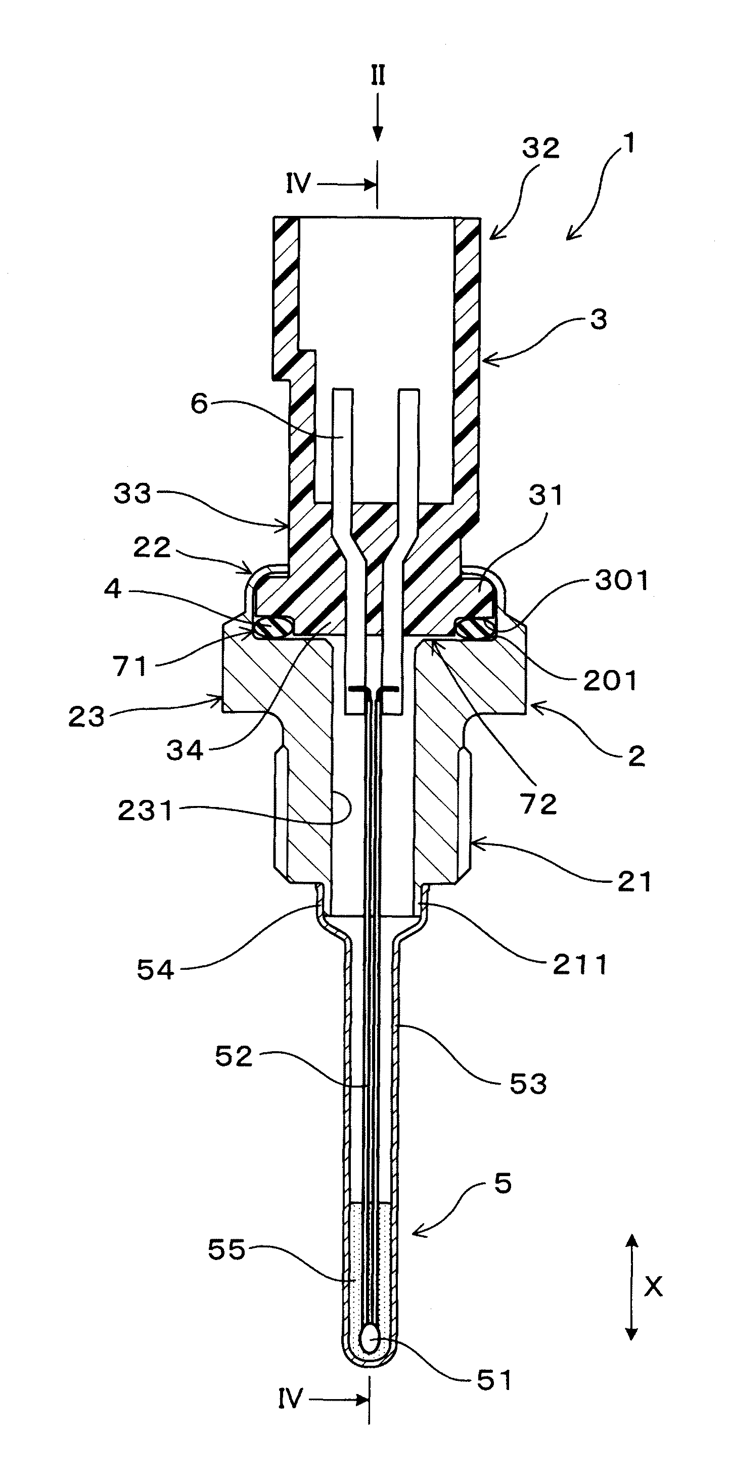
[0046]A temperature sensor 1 according to an embodiment of the invention is described with reference to FIGS. 1 to 5. As shown in FIG. 1, the temperature sensor 1 includes a temperature detecting section 5, a housing 2, a connector member 3 and a buffer member 4. The temperature detecting section 5 includes a temperature-sensitive element 51. The housing 2 is formed in a cylindrical shape and disposed on the proximal end side of the temperature detecting section 5. The connector member 3 is disposed on the proximal end side of the housing 2. The buffer member 4, which is elastically deformable, is disposed between the connector member 3 and the housing 2.

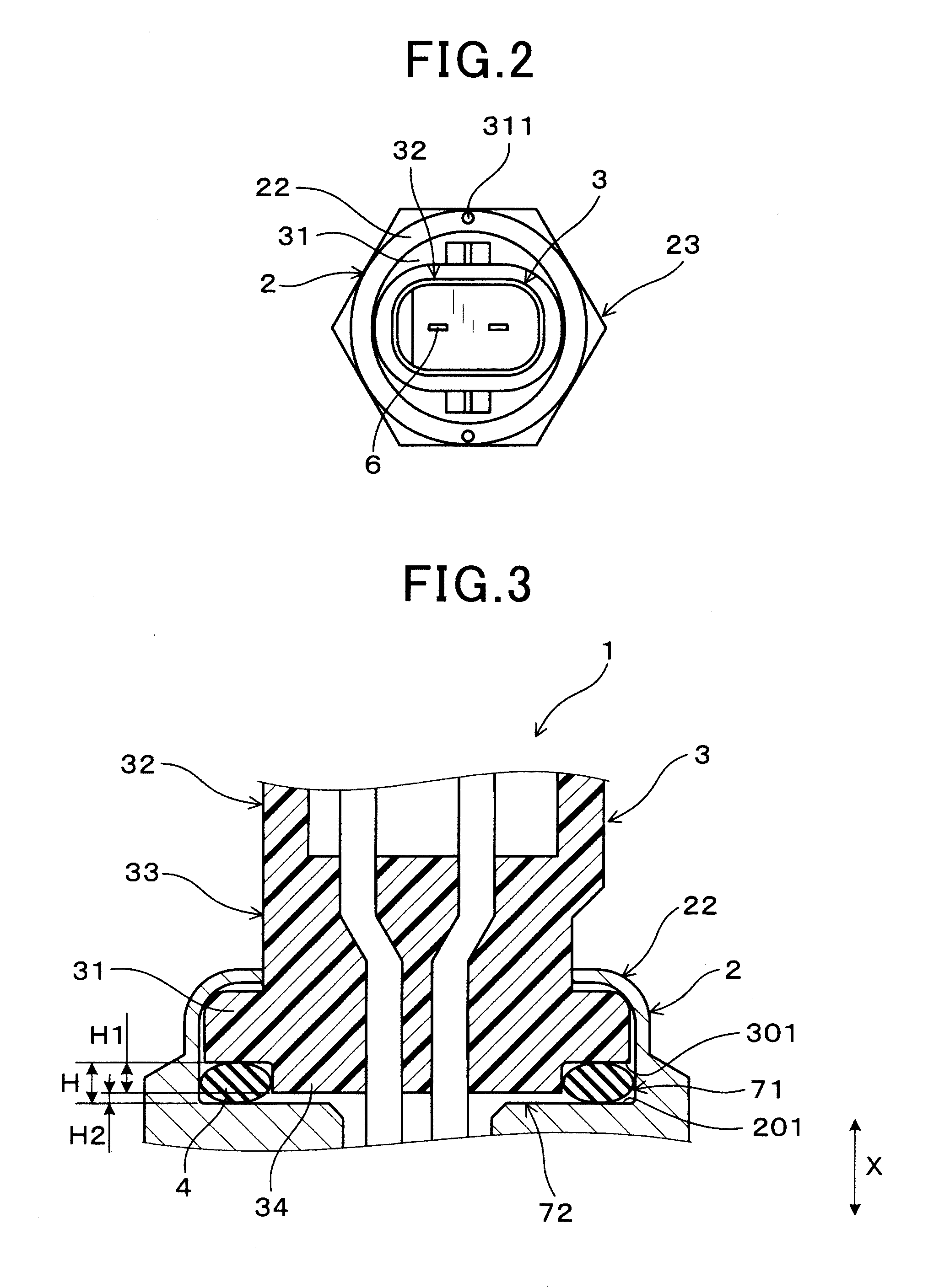
[0047]As shown in FIGS. 1 to 4, the connector member 3 includes a connector counter surface 301 located on the side of the housing 2 in the axial direction of the housing 2. The housing 2 includes a housing counter surface 201 located opposite to the connector counter surface 301. The buffer member 4 is disposed in a gap 71 formed b...


PUM

PropertyMeasurementUnit
Fractionaaaaaaaaaa
Fractionaaaaaaaaaa
Heightaaaaaaaaaa

Abstract

A temperature sensor includes a temperature detecting section including a temperature-sensitive element, a cylindrical housing disposed on a proximal end side of the temperature detecting section, a connector member disposed on a proximal end side of the housing, and a buffer member which is elastically deformable and disposed between the connector member and the housing. The connector member includes a connector counter surface located on a side of the housing in an axial direction along a longitudinal axis of the housing. The housing includes a housing counter surface located opposite to the connector counter surface. The housing counter surface and the connector counter surface are separated from each other so that a gap is present therebetween. The buffer member is disposed deformably in the gap so that the connector member and the housing are movable relative to each other in the axial direction.

Description

[0001]This application claims priority to Japanese Patent Application No. 2014-133464 filed on Jun. 30, 2014, and No. 2015-38315 filed on Feb. 27, 2015, the entire contents of which are hereby incorporated by reference.BACKGROUND OF THE INVENTION[0002]1. Field of the Invention[0003]The present invention relates to a temperature sensor and a process of manufacturing the temperature sensor.[0004]2. Description of Related Art[0005]Generally, internal combustion engines of vehicles are provided with a temperature sensor for measuring the temperature of exhaust gas and so on. Japanese Patent Application Laid-open No. H8-50061 describes a temperature sensor having a structure in which its connector is integrally fixed to its main body to reduce the manufacturing cost and to increases the productivity.[0006]More specifically, one end portion of the connector is inserted into a housing formed in a cylindrical shape, and integrally fixed to the housing by wrap-swaging the housing. The housin...

Claims


Application Information

Patent Timeline
IPC IPC(8): G01K1/08
CPCG01K2205/04G01K1/08
Inventor SHIBAYAMA, SUSUMU
Owner DENSO CORP
Why Eureka
Try Eureka