Optical image capturing system

an image capturing system and optical image technology, applied in the field of compact, can solve the problems that the optical image capturing system in the prior arts cannot meet the requirements of the higher-order camera lens module, and the problem of improving image quality becomes an important issue, so as to reduce the height of the optical system, improve image quality, and improve the effect of image quality

Active Publication Date: 2015-12-31
ABILITY OPTO ELECTRONICS TECH
View PDF1 Cites 91 Cited by
  • Summary
  • Abstract
  • Description
  • Claims
  • Application Information

AI Technical Summary

Benefits of technology

[0026]The height of optical system (HOS) can be reduced to achieve the minimization of the optical image capturing system when an absolute value of f1 is larger than f7 (|f1|>f7).
[0027]When |f / f1| is satisfied with the above conditions, the arrangement of the refractive power of the first lens element can avoid generating the abnormal aberration that cannot be corrected.
[0028]When a sum of |f2|, |f3|, |f4|, |f5|, and |f6| and a sum of |f1| and |f7| are satisfied with the above conditions, at least one of the second through sixth lens elements can has a weak positive refractive power or a weak negative refractive power. The weak refractive power indicates an absolute value of the focal length of a specific lens element is greater than 10. When at least one of the second through sixth lens elements has the weak positive refractive power, the positive refractive power of the first lens element can be shared, such that the unnecessary aberration will not appear too early. On the contrary, when at least one of the second through sixth lens elements has the weak negative refractive power, the aberration of the optical image capturing system can be corrected and fine tuned.
[0029]When InRS72 / TP7 is satisfied with the above conditions, it's favorable for manufacturing and forming the lens element and for maintaining the minimization for the optical image capturing system. Beside, the seventh lens element may have a negative refractive power and the concave image-side surface. Hereby, the back focal length is reduced for maintaining the miniaturization, so as to miniaturize the lens element effectively. In addition, at least one of the object-side and the image-side surfaces of the seventh lens elements may have at least one inflection point, such that the angle of incident with incoming light from an off-axis view field can be suppressed effectively and the aberration in the off-axis view field can be corrected further.

Problems solved by technology

The optical image capturing system in prior arts cannot meet the requirement of the higher order camera lens module.
Therefore, an optical imaging system capable of increasing an incoming light quantity of optical system as well as improving the image quality becomes an important issue.

Method used


Image

  • Optical image capturing system
  • Optical image capturing system
  • Optical image capturing system

Examples


first embodiment

The First Embodiment

Embodiment 1

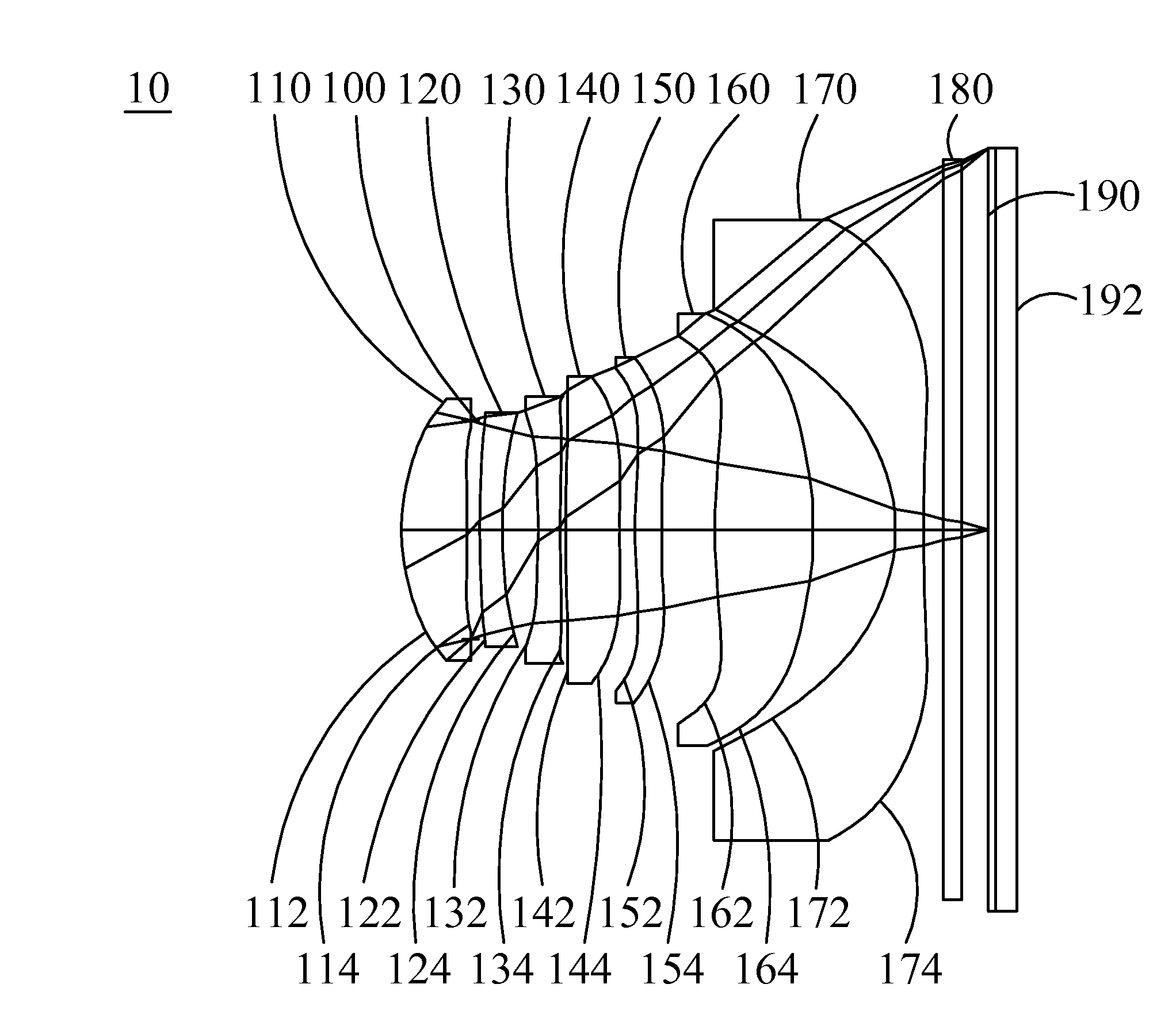
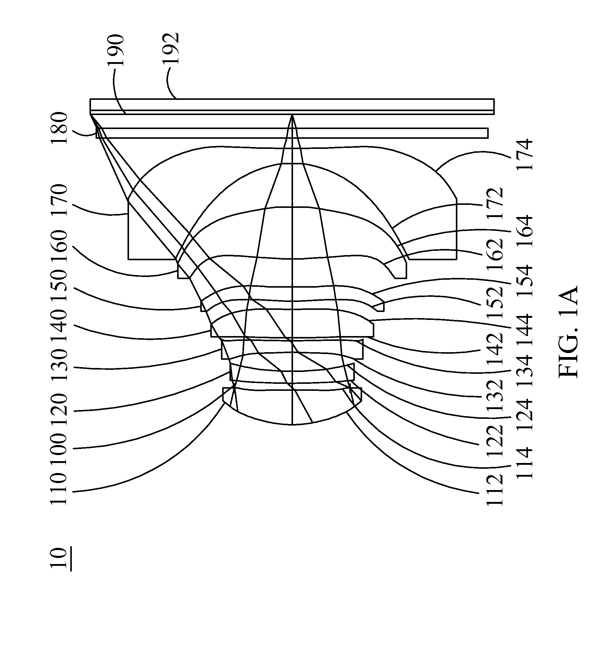
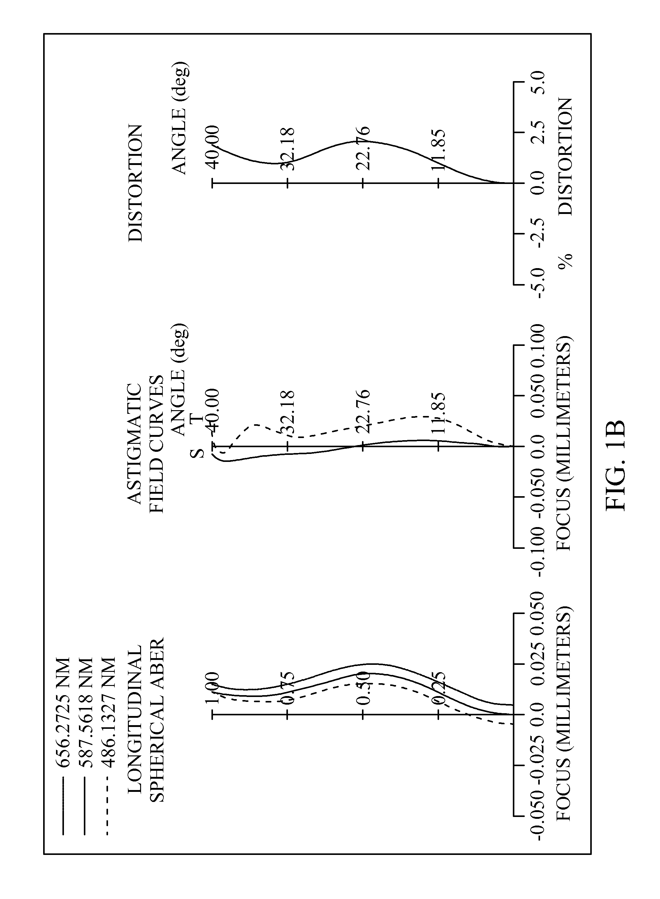
[0085]Please refer to FIG. 1A, FIG. 1B, and FIG. 1C, FIG. 1A is a schematic view of the optical image capturing system according to the first embodiment of the present application, FIG. 1B is longitudinal spherical aberration curves, astigmatic field curves, and an optical distortion curve of the optical image capturing system in the order from left to right according to the first embodiment of the present application, and FIG. 1C is a TV distortion grid of the optical image capturing system according to the first embodiment of the present application. As shown in FIG. 1A, in order from an object side to an image side, the optical image capturing system includes a first lens element 110, an aperture stop 100, a second lens element 120, a third lens element 130, a fourth lens element 140, a fifth lens element 150, a sixth lens element 160, a seventh lens element 170, an IR-bandstop filter 180, an image plane 190, and an image sensing device 192.

[0086]T...

second embodiment

The Second Embodiment

Embodiment 2

[0124]Please refer to FIG. 2A, FIG. 2B, and FIG. 2C, FIG. 2A is a schematic view of the optical image capturing system according to the second embodiment of the present application, FIG. 2B is longitudinal spherical aberration curves, astigmatic field curves, and an optical distortion curve of the optical image capturing system in the order from left to right according to the second embodiment of the present application, and FIG. 2C is a TV distortion grid of the optical image capturing system according to the second embodiment of the present application. As shown in FIG. 2A, in order from an object side to an image side, the optical image capturing system includes an aperture stop 200, a first lens element 210, a second lens element 220, a third lens element 230, a fourth lens element 240, a fifth lens element 250, a sixth lens element 260, a seventh lens element 270, an IR-bandstop filter 280, an image plane 290, and an image sensing device 292.

[01...

third embodiment

The Third Embodiment

Embodiment 3

[0142]Please refer to FIG. 3A, FIG. 3B, and FIG. 3C, FIG. 3A is a schematic view of the optical image capturing system according to the third embodiment of the present application, FIG. 3B is longitudinal spherical aberration curves, astigmatic field curves, and an optical distortion curve of the optical image capturing system in the order from left to right according to the third embodiment of the present application, and FIG. 3C is a TV distortion grid of the optical image capturing system according to the third embodiment of the present application. As shown in FIG. 3A, in order from an object side to an image side, the optical image capturing system includes an aperture stop 300, a first lens element 310, a second lens element 320, a third lens element 330, a fourth lens element 340, a fifth lens element 350, a sixth lens element 360, a seventh lens element 370, an IR-bandstop filter 380, an image plane 390, and an image sensing device 392.

[0143]T...


PUM


Abstract

The invention discloses a seven-piece optical lens for capturing image and a seven-piece optical system for capturing image. In order from an object side to an image side, the optical lens along the optical axis comprises a first lens with refractive power having a convex object-side surface; a second lens with refractive power, a third lens with refractive power; a fourth lens with refractive power; a fifth lens with refractive power, a sixth lens with refractive power, and a seventh lens with negative refractive power; and at least one of the image-side surface and object-side surface of each of the seven lens elements is aspheric. The optical lens can increase the aperture value and improve the imagining quality for use in compact cameras.

Description

CROSS-REFERENCE TO RELATED APPLICATION[0001]This application claims the benefit of Taiwan Patent Application No. 103121996, filed on Jun. 25, 2014, in the Taiwan Intellectual Property Office, the disclosure of which is incorporated herein in its entirety by reference.BACKGROUND OF THE INVENTION[0002]1. Field of the Invention[0003]The present disclosure relates to an optical image capturing system, and more particularly to a compact optical image capturing system which can be applied to electronic products.[0004]2. Description of the Related Art[0005]In recent years, with the rise of portable electronic devices having camera functionalities, the demand for an optical image capturing system is raised gradually. The image sensing device of ordinary photographing camera is commonly selected from charge coupled device (CCD) or complementary metal-oxide semiconductor sensor (CMOS Sensor). In addition, as advanced semiconductor manufacturing technology enables the minimization of pixel siz...

Claims


Application Information

Patent Timeline
Patent Type & Authority Applications(United States)
IPC IPC(8): G02B13/00G02B9/64
CPCG02B9/64G02B13/0045
Inventor TANG, NAI-YUANCHANG, YEONG-MING
Owner ABILITY OPTO ELECTRONICS TECH
Why Eureka
Try Eureka