Cell connector and battery cell, battery module, battery, battery system, vehicle and method for producing a battery module

Active Publication Date: 2015-12-31
ROBERT BOSCH GMBH
View PDF4 Cites 4 Cited by
  • Summary
  • Abstract
  • Description
  • Claims
  • Application Information

AI Technical Summary

Benefits of technology

[0024]Expediently, the clamping can comprise suspending the first engagement section in the first receiving section and then suspending the second engagement section in the second receiving section. As a result, the connection can be improved.
[0025]Expediently, the clamping can furthermore comprise pressing down the second limb section once the first engagement section has been suspended. As a result, in particular when the clip element is designed in a sprung manner, the connection can be further improved.
[0026]Expediently, the suspension of the second engagement section can comprise displacement of the clip element whilst maintaining the engagement of the first engagement section in the first receiving section. As a result, the connection can be further impro

Problems solved by technology

The battery systems need to meet very stringent requirements as regards the usable energy content, the charging/disch

Method used


Image

  • Cell connector and battery cell, battery module, battery, battery system, vehicle and method for producing a battery module
  • Cell connector and battery cell, battery module, battery, battery system, vehicle and method for producing a battery module
  • Cell connector and battery cell, battery module, battery, battery system, vehicle and method for producing a battery module

Examples


Example

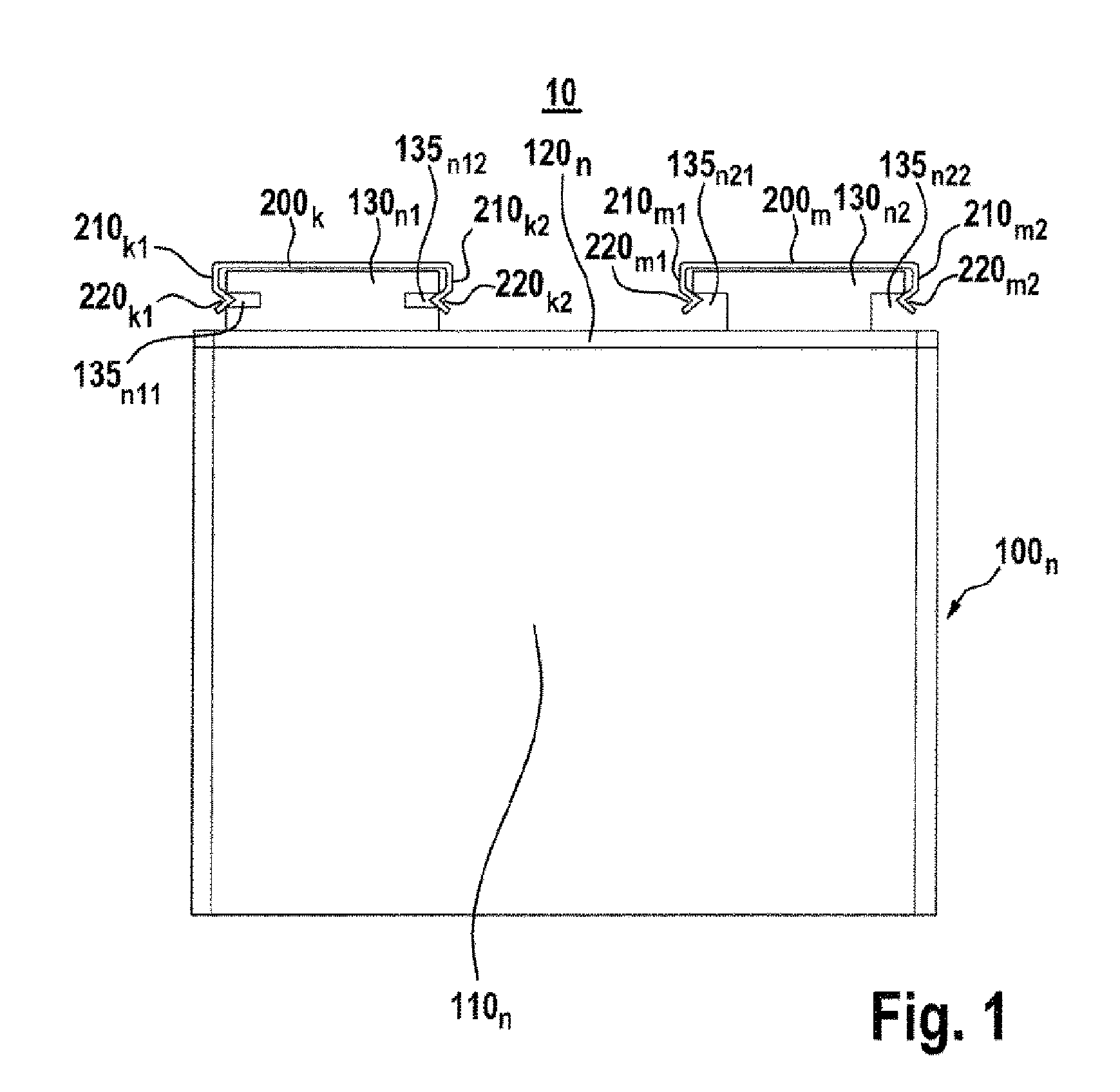
[0040]FIG. 1 shows a schematic side view of a battery module 10 comprising clip elements 200k, 200m in accordance with one embodiment of the invention.

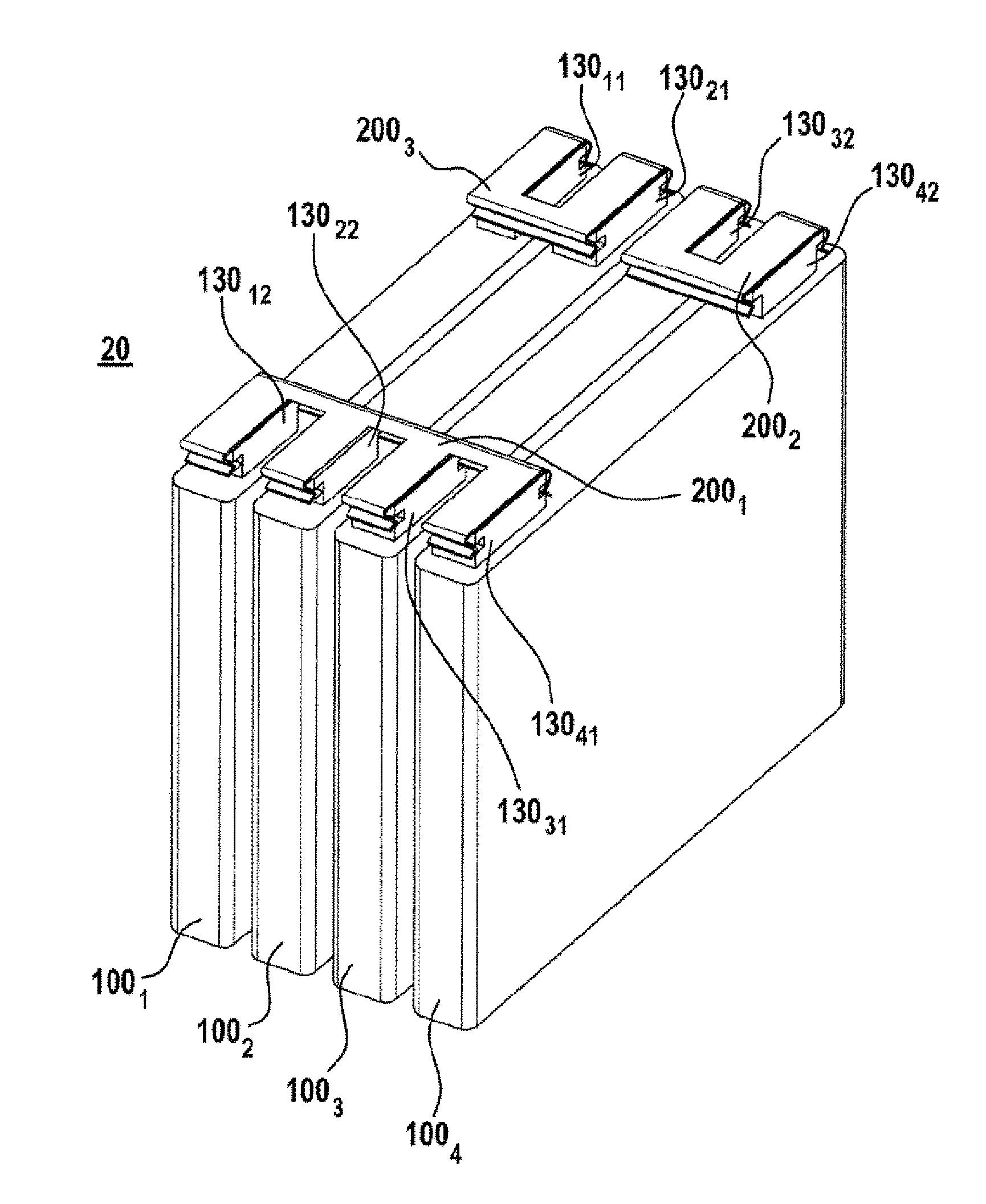
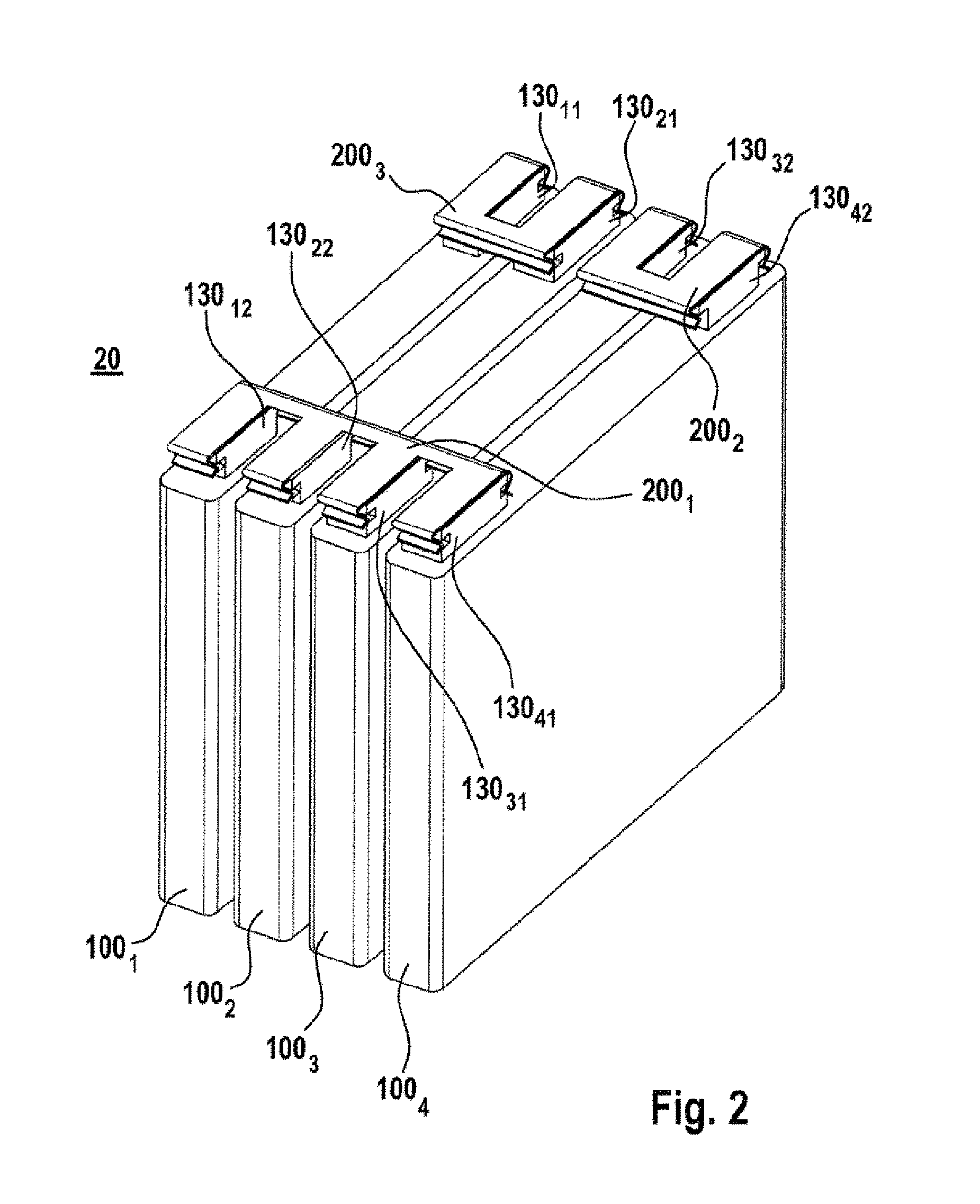
[0041]As shown by way of example in FIG. 1, the battery module 10 comprises a battery cell 100n having a first cell terminal 130n1 and a second cell terminal 130n2 and a first clip element 200k, and a second clip element 200m, which are each arranged on the cell terminals 130n1, 130n2. The cell terminals 130n1, 130n2 act as electrical connections, i.e. positive terminal and negative terminal, are each rectangular and each comprise two receiving sections 135n11, 135n21, 135n12, 135b22, arranged opposite one another. As shown by way of example in FIG. 1, the first cell terminal 130n1 is formed prismatically with two slots (H-shaped) and the second cell terminal 130n2 is T-shaped.

[0042]The clip elements 200k, 200m for fastening the cell connector each comprise a back section, a first limb section 210k1, 210m1, which is formed at a first ...


PUM


Abstract

Cell connector for an electrical or mechanical connection of cell terminals of battery cells, characterized by a clip element for fastening the cell connector to the cell terminals comprising a back section, a first limb section which is formed at a first end of the back section, having a first engagement section, and a second limb section, which is formed at a second end of the back section and is formed so as to be spaced apart from and opposite the first limb section, having a second engagement section, wherein the clip element is designed in such a way that it can at least partially surround the cell terminals.

Description

BACKGROUND OF THE INVENTION[0001]It is conceivable that increasingly new battery systems (rechargeable battery systems) for example with lithium-ion rechargeable batteries, lithium-polymer rechargeable batteries or nickel-metal hybrid rechargeable batteries, are used increasingly both in stationary applications, for example in wind turbines, and in mobile applications, for example in electric motor vehicles (electric vehicles, EVs) or hybrid vehicles (hybrid electric vehicles, HEV), as rechargeable electrical energy stores (EES).[0002]The battery systems need to meet very stringent requirements as regards the usable energy content, the charging / discharging efficiency, the reliability, the life and the undesirable loss of capacity owing to frequent partial discharge.[0003]A battery system comprises a large number of battery cells. Owing to their cell internal resistance and the electrochemical processes occurring, the battery cells heat up during charging and discharging. The battery...

Claims


Application Information

Patent Timeline
IPC IPC(8): H01M2/20H01M50/507H01M50/514H01M50/55H01M50/553
CPCH01M2/206H01M2220/10H01M2220/20H01M50/553H01M50/55H01M50/507H01M50/514Y02E60/10
Inventor OECHSLE, MATTHIASAKTUERK, SEREF
Owner ROBERT BOSCH GMBH
Why Eureka
Try Eureka