

Transmission control device and transmission control method
- Summary
- Abstract
- Description
- Claims
- Application Information
AI Technical Summary
Benefits of technology
Problems solved by technology
Method used
Image

Examples
first embodiment
[0025]Now, a transmission control device according to a first embodiment of the present invention is described with reference to FIG. 2 to FIG. 8. The same reference numeral used throughout FIG. 2 to FIG. 8 represents the same component.
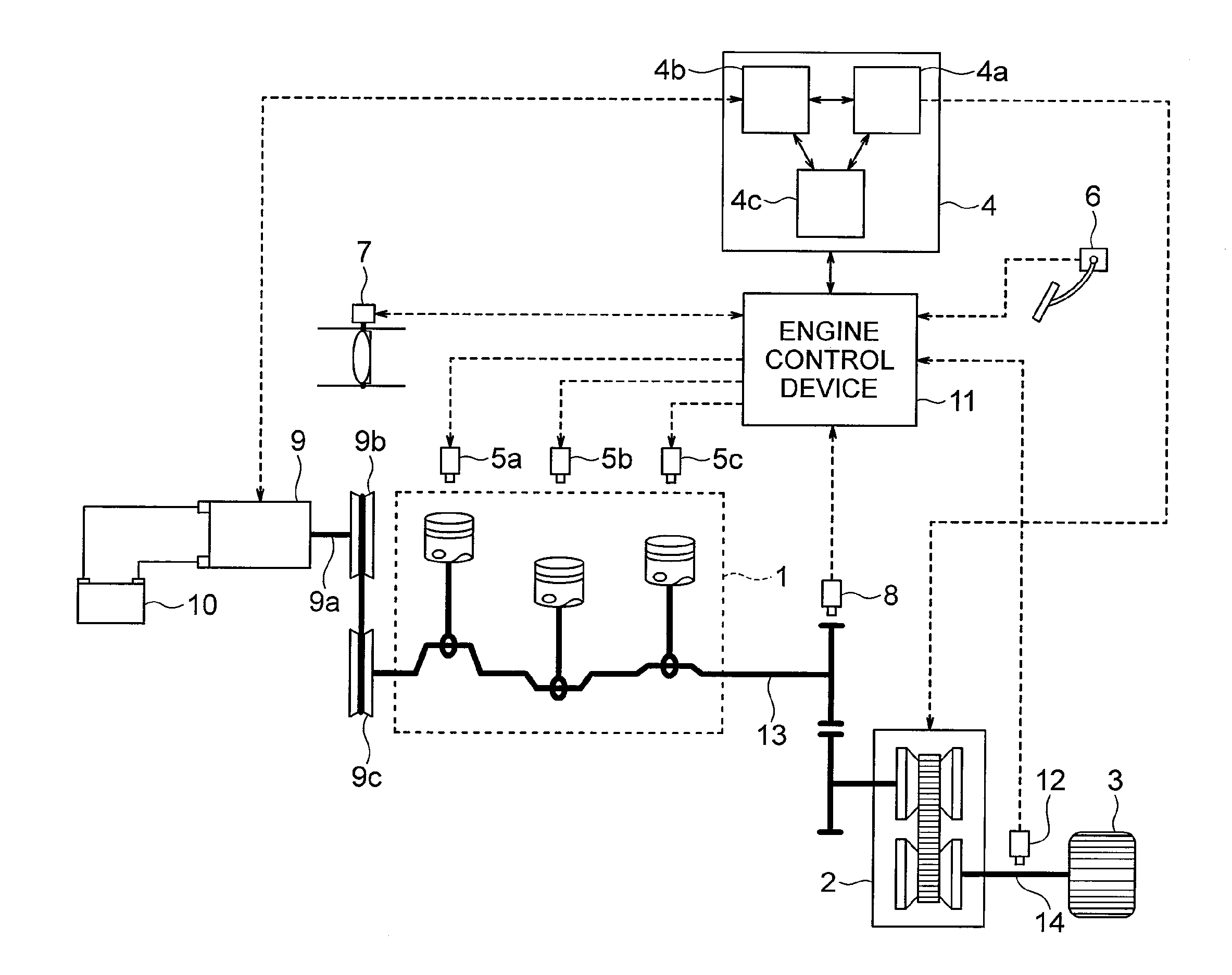
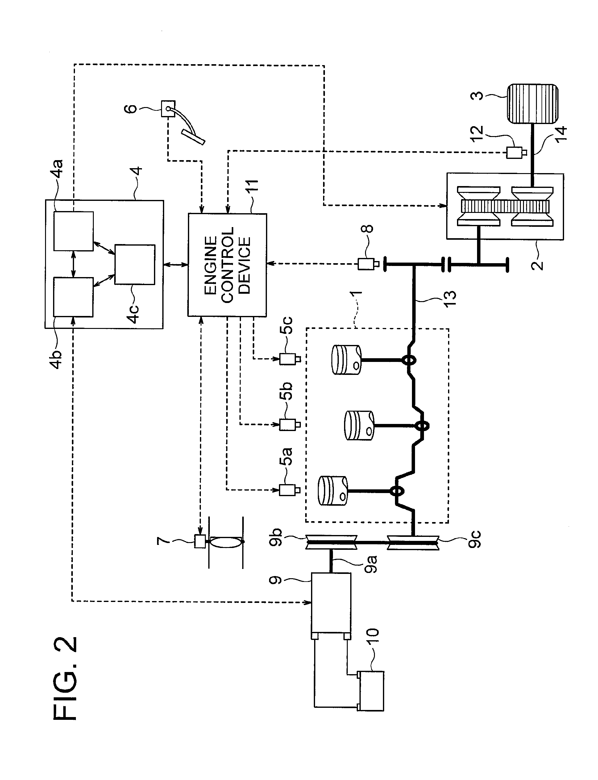
[0026]FIG. 2 is a configuration diagram for illustrating the configuration of the transmission control device according to the first embodiment of the present invention. In FIG. 2, reference numeral 1 represents an engine. Injectors 5a, 5b, and 5c for injecting fuel are provided to the engine 1. The engine 1 causes a vehicle to run by obtaining power through fuel combustion and transmitting the obtained power to a wheel 3 (automobile tire). Reference numeral 9 represents an electric motor. The electric motor 9 includes a mechanical output shaft 9a connected to the engine 1 via pulleys 9b and 9c. The electric motor 9 applies a torque to the engine 1 with use of electric power of a battery 10 (electric storage device), and converts the rotational force...
PUM
 Abstract
Description
Claims
Application Information