
Method for calculating a desired yaw rate for a vehicle

Active Publication Date: 2016-01-07
VOLVO LASTVAGNAR AB
View PDF9 Cites 5 Cited by
  • Summary
  • Abstract
  • Description
  • Claims
  • Application Information

AI Technical Summary

Benefits of technology

The patent describes a system that helps drivers keep control of their vehicles when they start to lose control in the yaw plane (when the vehicle is tilting too much). This system, called Electronic Stability Control (ESC), detects when there is a problem with the vehicle's movement and then applies brakes to stabilize it. The patent also uses a computer program to create a safer control system for vehicles in these severe situations. Overall, this system helps drivers keep their cars under control and reduces the risk of accidents.

Problems solved by technology

When operating a vehicle there is a risk that the driver loses control of the vehicle's motion in the yaw plane, typically due to insufficient road friction resulting in that the vehicle may understeer or oversteer.
A drawback with existing ESC-systems is that the desired yaw rate is not always estimated satisfyingly well, especially when the vehicle is in more severe situations of yaw instability.
Therefore, a conventional ESC system would misinterpret the driver's intentions completely.

Method used


Image

  • Method for calculating a desired yaw rate for a vehicle
  • Method for calculating a desired yaw rate for a vehicle
  • Method for calculating a desired yaw rate for a vehicle

Examples


Embodiment Construction

[0043]The present invention will now be described more fully hereinafter with reference to the accompanying drawings, in which currently preferred embodiments of the invention are shown. This invention may, however, be embodied in many different forms and should not be construed as limited to the embodiments set forth herein; rather, these embodiments are provided for thoroughness and completeness, and fully convey the scope of the invention to the skilled addressee. Like reference characters refer to like elements throughout.

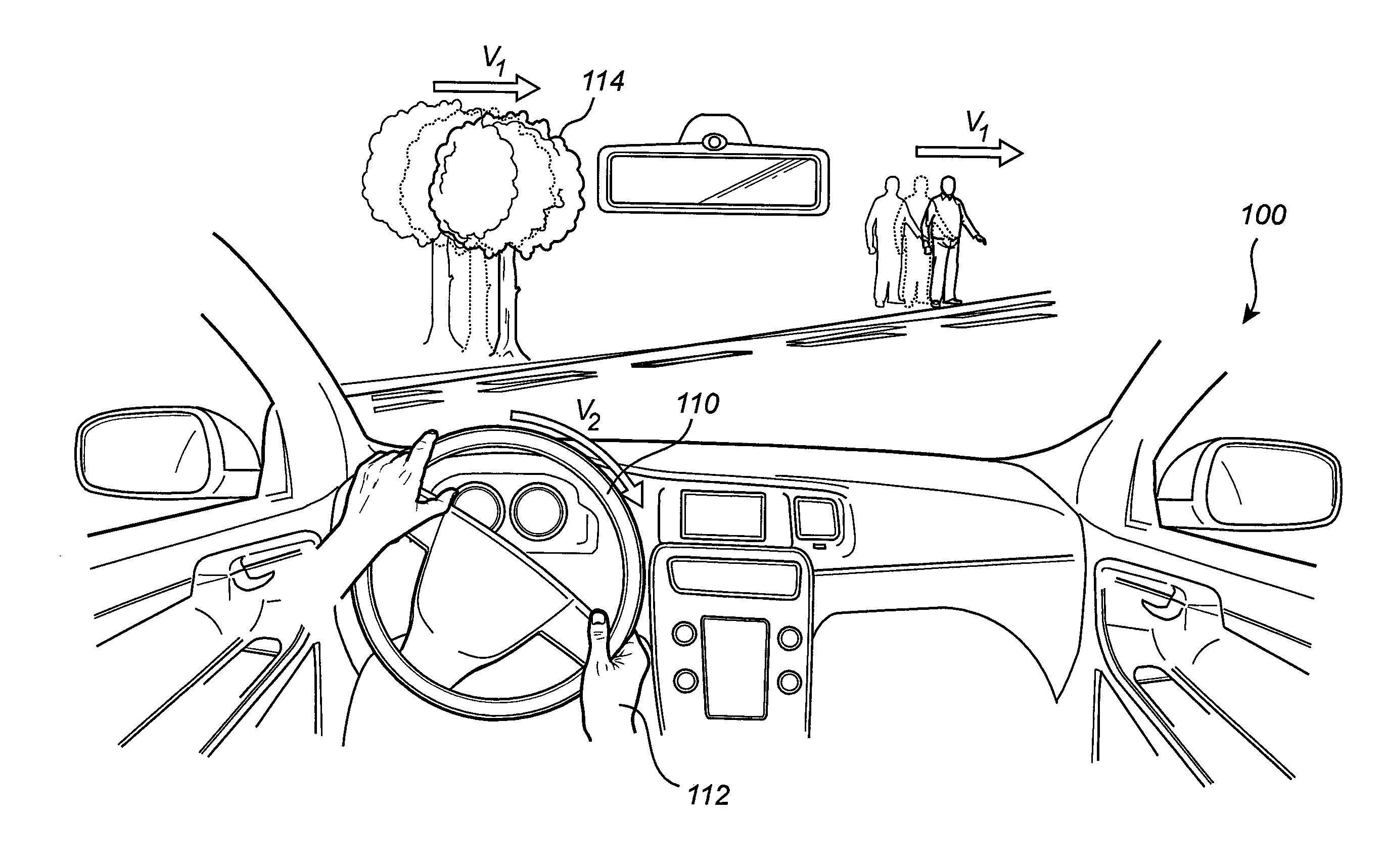
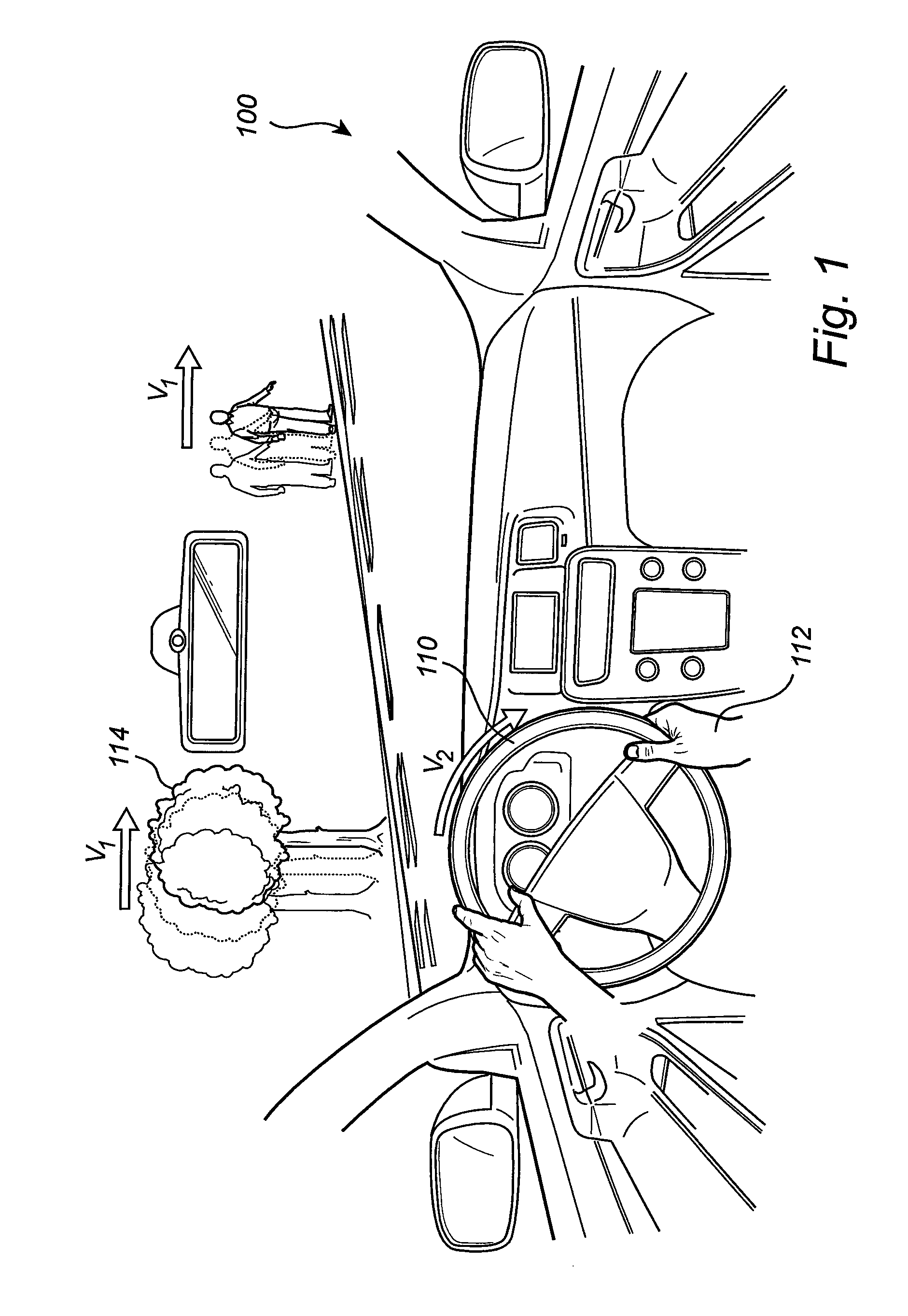
[0044]As is illustrated in FIG. 1 the concept is based on that the driver will rotate the steering wheel 110 in with a rotational speed V2 when desiring to achieve a change in the vehicle's 100 yaw rate. Further, the method described herein is based on that the driver will apply a rate of steering wheel rotation as a function of the driver's perceived error in yaw rate. In FIG. 1, the environment 114 is perceived to move in a speed Vi due to a skidding state of...


PUM


Abstract

A method is provided for calculating a driver's desired yaw rate of a vehicle for use in a vehicle movement control system and includes determining the current yaw rate of the vehicle, determining the rate of the vehicle's steering wheel rotation. The method further includes calculating a first desired yaw rate of the vehicle based on the determined current yaw rate of the vehicle and the determined rate of the vehicle's steering wheel rotation, the desired yaw rate being further calculated based on the assumption that the driver applies a rate of steering wheel rotation as function of the driver's perceived error in yaw rate, and finally the step of providing the first desired yaw rate as an input to the vehicle movement control system for controlling the vehicle.

Description

BACKGROUND AND SUMMARY[0001]The present invention relates to a vehicle control system and a corresponding method for determining a driver's desired yaw rate of a vehicle.[0002]When operating a vehicle there is a risk that the driver loses control of the vehicle's motion in the yaw plane, typically due to insufficient road friction resulting in that the vehicle may understeer or oversteer. To assist the driver in keeping control of the vehicle's yaw motion, modem vehicles are equipped with different vehicle movement control systems such as Electronic Stability Control (ESC) systems. Generally, ESC systems detect yaw instabilities by comparing an actual yaw motion in the yaw plane of the vehicle with a desired yaw rate. Subsequently, the ESC system reduces any differences between actual and desired yaw motions by applying brake pressures in a controlled manner at the individual wheels of the vehicle.[0003]The desired yaw rate is generally calculated based on the front wheel steering a...

Claims


Application Information

Patent Timeline
IPC IPC(8): B60W30/02B60W40/114
CPCB60W40/114B60W2520/14B60W30/02B62D6/003B62D6/005B60W10/18B60W10/20B60W30/045B60W2050/0033B60W2050/0075B60W2556/10B60W30/18
Inventor MARKKULA, GUSTAV
Owner VOLVO LASTVAGNAR AB
Learn More