Means of Water Surface Transport

Active Publication Date: 2016-01-07
CHEN ZHENCHENG
View PDF4 Cites 0 Cited by
  • Summary
  • Abstract
  • Description
  • Claims
  • Application Information

AI Technical Summary

Benefits of technology

[0008]The water surface transport means provided in the embodiments of the present invention can be free from great water resistance to the greatest extent to increase its speed and meanwhile can make full use of hydrodynamic buoyancy stirred up by its own movement to load a self-weight and a load so as to satisfy the demands of various tonnages, utilizing useless energy dissipated by water wave movement to be converted into hydrodynamic propulsive force to accomplish useful work, thereby highly improving the speed and course stability, and utilizing hydrodynamic lift to improve longitudinal and lateral stability. The layout of a surge diversion groove top line that is lower in the front and higher in the rear is used to focus hydrodynamic centrifugal force on the stern when

Problems solved by technology

General displacement vessels, which have good stability and can satisfy the demands of large-, medium- or small-tonnage, but due to deep draft, big water resistance and the larger the tonnage is, the deeper the draft is, have high energy consumption so that it is difficult to improve the speed.
Hydrofoil crafts, which have reduced water resistance due to shallow draft so that the speed is improved but have weaker maneuverability, seaworthiness and dirigibility and are difficult to navigate in fast-flowing, shallow watercourse and to navigate steadily in strong wind and big waves.
Hovercrafts, which are free from water resistance so that the speed is improved, but need large power to generate air cushion and have high energy consumption so that it is uneconomical to use them in passenger and cargo transport.
In addition, hovercrafts have weak anti-wave performance, and in particular, its advantage disappears under the attack of crosswind.
General planing crafts, which have shallow draft duri

Method used


Image

  • Means of Water Surface Transport
  • Means of Water Surface Transport
  • Means of Water Surface Transport

Examples


Example

[0029]The embodiments of the present invention will be described in detail below in conjunction with accompanying drawings. It should be illustrated that, without conflict, the embodiments in the present application and the features in the embodiments can be combined with each other randomly.

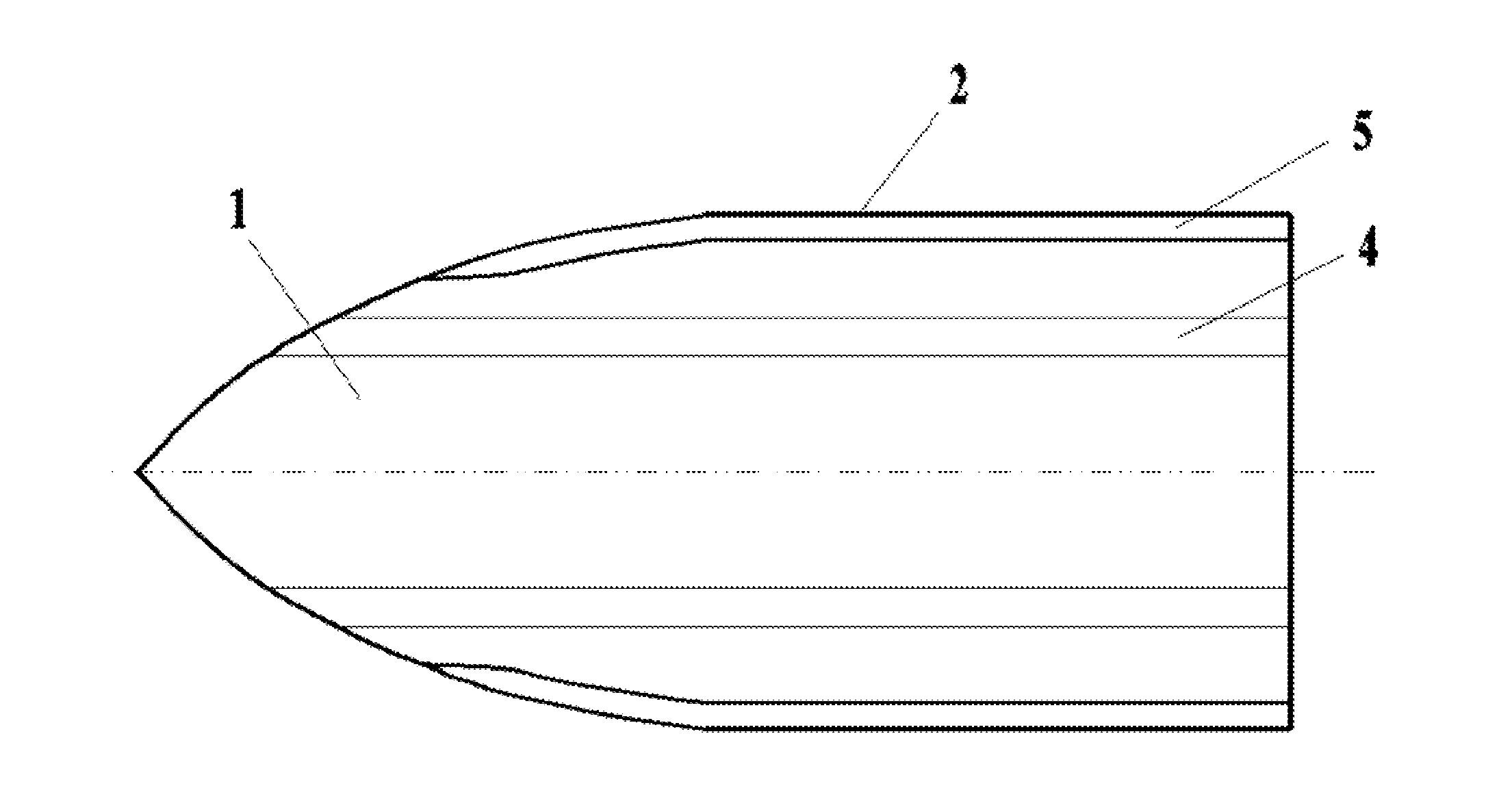
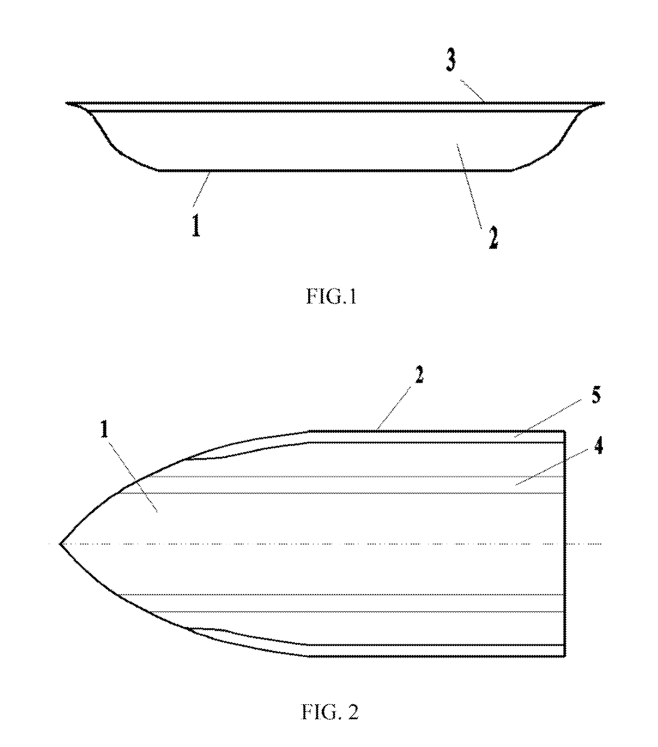
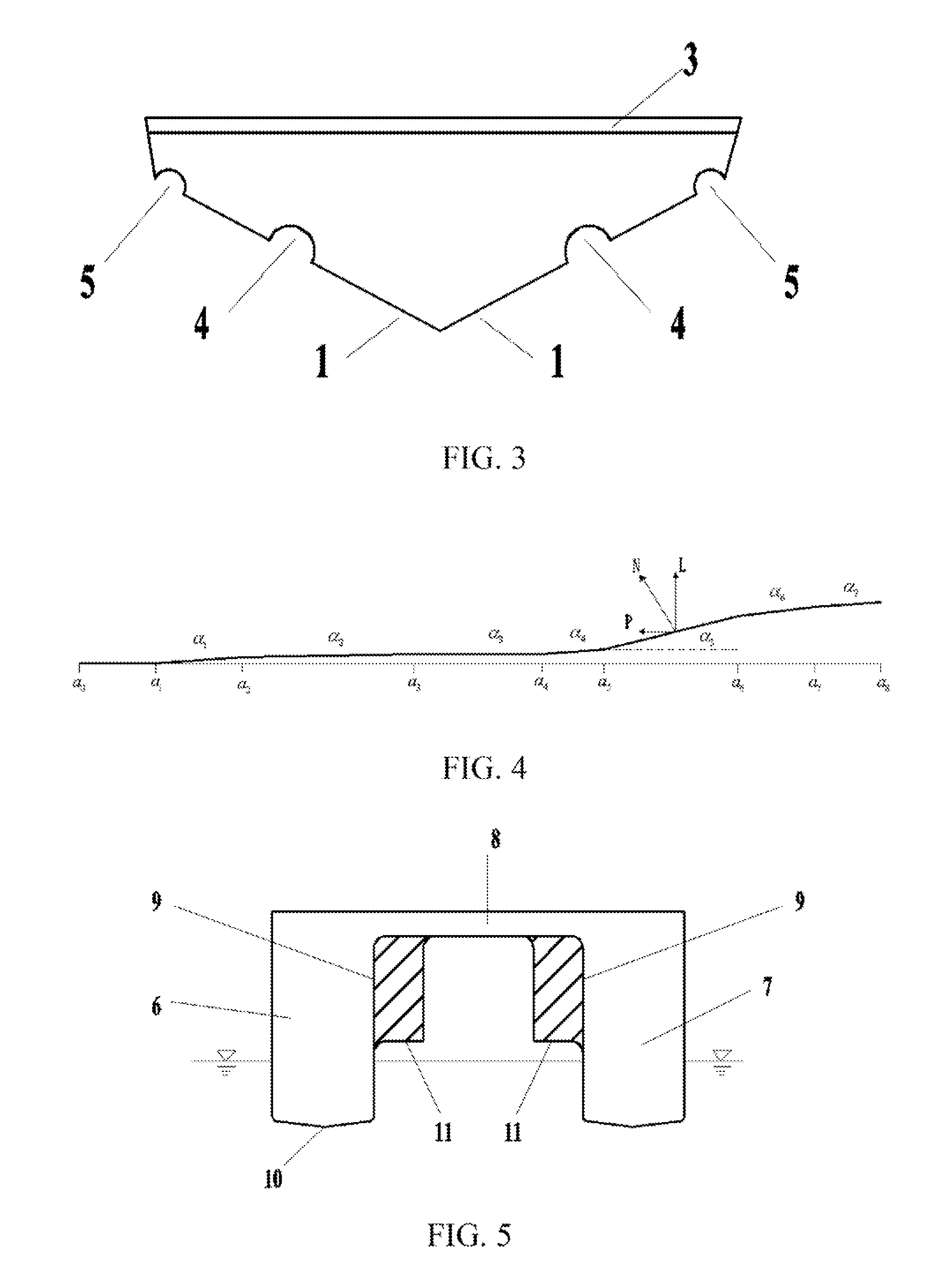
[0030]FIGS. 1-4 show structural diagrams of a mono-hull water surface transport means according to the embodiments of the present invention, FIG. 1 is a side view, FIG. 2 is a bottom view, FIG. 3 is a rear view, and FIG. 4 is a structural diagram of top lines of the surge diversion grooves and the wave suppression diversion baffles. Reference sign 1 represents a hull bottom, reference sign 2 represents hull sides, reference sign 3 represents a deck, reference sign 4 represents surge diversion grooves and reference sign 5 represents wave suppression diversion baffles; a0-a8 represent projections of the knots with the tilt angle changes of a top line on the baseline of the hull bottom, and α1-α8 r...


PUM


Abstract

A water surface transport means, comprising a bottom (1), boards (2), a deck (3), surge diversion grooves (4) and wave suppression diversion baffles (5), the surge diversion groove (4) being provided in a space between a bottom surface vertically recessed into the hull bottom (1) and the deck (3) and extending from the bow to the stern, with an arc-shaped transverse section and a top line of longitudinal section being lower in the front and higher in the rear; a top transverse section of the wave suppression diversion baffle (5) being arc-shaped and a top line of longitudinal section being lower in the front and higher in the rear. The water surface transport means can be configured as mono-hull, catamaran and trimaran.

Description

TECHNICAL FIELD[0001]The embodiments of the present invention relate to a water surface transport means used in the technical field of waterway transport.BACKGROUND OF THE RELATED ART[0002]At present, vehicles used for waterway transport, i.e., all sorts of vessels, include:[0003]General displacement vessels, which have good stability and can satisfy the demands of large-, medium- or small-tonnage, but due to deep draft, big water resistance and the larger the tonnage is, the deeper the draft is, have high energy consumption so that it is difficult to improve the speed.[0004]Hydrofoil crafts, which have reduced water resistance due to shallow draft so that the speed is improved but have weaker maneuverability, seaworthiness and dirigibility and are difficult to navigate in fast-flowing, shallow watercourse and to navigate steadily in strong wind and big waves.[0005]Hovercrafts, which are free from water resistance so that the speed is improved, but need large power to generate air c...

Claims


Application Information

Patent Timeline
IPC IPC(8): B63B1/12B63B1/04B63B3/00
CPCB63B1/042B63B3/00B63B1/125B63B2001/208B63B2001/201
Inventor CHEN, ZHENCHENG
Owner CHEN ZHENCHENG
Why Eureka
Try Eureka