Multi-mode Passive Infrared Occupancy Sensor System For Energy Saving Application

Active Publication Date: 2016-01-07
FRED KATZ CONSULTING INC
View PDF16 Cites 36 Cited by
  • Summary
  • Abstract
  • Description
  • Claims
  • Application Information

AI Technical Summary

Benefits of technology

[0006]The invention provides a multi-mode passive infrared (PIR) motion sensor and non-contact temperature sensor system that operates to detect a presence of a person typing, reading or even sleeping in a chair, couch or bed or just standing without the need for continuous motion. As such, the inventive PIR occupancy sensor system accurately maintains the room's status as ‘occupied’ or ‘unoccupied’. When detecting that a room or monitored zone is occupied even where the occupant is substantially dormant, the inventive PIR occupancy sensor system controls the pathway for electrical power delivered to the room or zone, maintaining the lights, heat and / or air conditioning, or other service, in an “on” state rather than being automatically switched off by a wrongful determination that the room is no longer occupied.

Problems solved by technology

When a person is seated at a desk, however, the person's motion may be so slight (micro-motion) that it is insufficient to properly trigger a PIR motion detector (the backbone of conventional room occupancy sensors) to maintain the occupied state and the supply of current to the room or monitored zone.
So where further “presence” detection is required to maintain an occupied status, the occupancy sensor may change the status to “unoccupied” by failure to detect small micro-motions and consequently inadvertently interrupt the source of electrical power.

Method used


Image

  • Multi-mode Passive Infrared Occupancy Sensor System For Energy Saving Application
  • Multi-mode Passive Infrared Occupancy Sensor System For Energy Saving Application
  • Multi-mode Passive Infrared Occupancy Sensor System For Energy Saving Application

Examples


Embodiment Construction

[0028]The following is a detailed description of example embodiments of the invention depicted in the accompanying drawings. The example embodiments are presented in such detail as to clearly communicate the invention and are designed to make such embodiments obvious to a person of ordinary skill in the art. However, the amount of detail offered is not intended to limit the anticipated variations of embodiments; on the contrary, the intention is to cover all modifications, equivalents, and alternatives falling within the spirit and scope of the present invention, as defined by the appended claims.

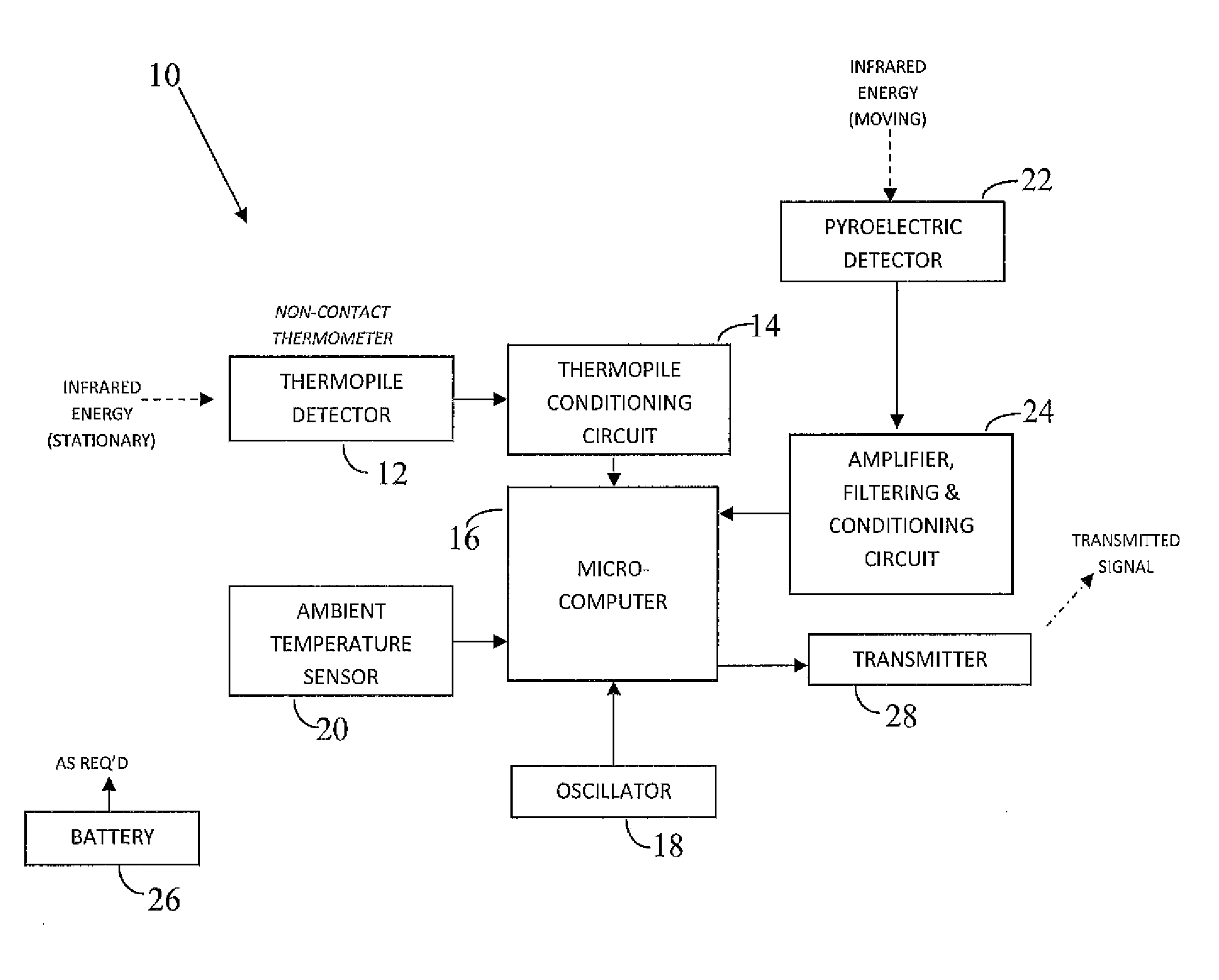
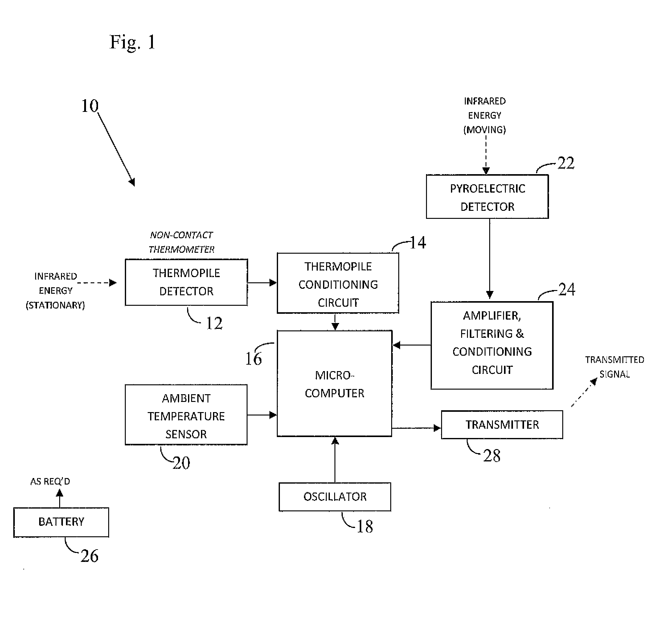
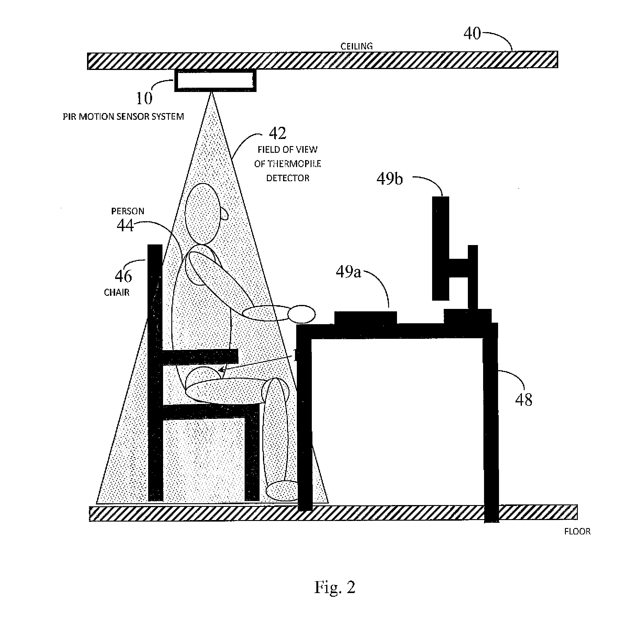
[0029]Inventive operation of the inventive PIR occupancy sensor system is supported by non-contact temperature measurement means that is focused upon an area, room or monitored zone where a person is likely to be sitting or standing and a processing function or controller that compares the temperature measured at the focused upon area to a measured ambient air temperature in the monitored z...


PUM


Abstract

A passive infrared (PIR) motion sensor system includes a non-contact thermopile detector for capturing infrared energy from a focused upon area in a room or zone deemed most likely to be occupied and generating a thermopile temperature signal therefrom, a pyroelectric detector for viewing through multiple passive lens elements (lenslets) that form PIR beams from a large portion of the room or zone and generating a pyroelectric signal therefrom, an ambient temperature sensor for sensing an ambient temperature in the room or zone and generating an ambient temperature signal detection threshold that is utilized in PIR detection therefrom and a microcomputer configured to process the thermopile temperature signal, the pyroelectric signal and the ambient temperature signal and determine whether the room or zone is occupied or unoccupied. An electrical current supply or occupied signal is transmitted to the room or zone is maintained when the microcomputer determines that the room or zone is still occupied and is interrupted when the microcomputer determines that the room or zone is unoccupied.

Description

CROSS-REFERENCE TO A RELATED APPLICATIONS[0001]The invention described and claimed hereinbelow claims priority under 35 USC §120 from U.S. Provisional Patent Application Ser. No. 62 / 020,666, filed on Jul. 3, 2014, the contents of which are incorporated by reference herein.BACKGROUND OF THE INVENTION[0002]Many known room occupancy sensors use Passive Infrared (PIR) motion sensors (sometimes commonly referred to as occupancy sensors) located on the ceiling and / or wall and / or near a doorway in a room to determine whether a person is present in the room and control the lighting and / or environmental conditions in the room accordingly. For example, known occupancy sensors sense a person entering a previously unoccupied room when the entering person traverses one or more PIR beams from a PIR motion detector positioned to monitor a doorway and based on the sensing, actuates or enables the room's lighting in the occupied state to illuminate the room. Subsequent motion in the room by the occu...

Claims


Application Information

Patent Timeline
Patent Type & Authority Applications(United States)
IPC IPC(8): F24F11/00G05B15/02
CPCF24F11/0034F24F2011/0035G05B15/02F24F11/30F24F2120/10F24F2120/12F24F11/46
Inventor KATZ, FRED
Owner FRED KATZ CONSULTING INC
Why Eureka
Try Eureka