Optical image stabilizer detecting x direction displacement and y direction displacement of lens group

a stabilizer and optical technology, applied in the field of optical image stabilizers, can solve the problems of excessively small linear component of the signal generated by each hall sensor, and the need for af modules to be tilted in the opposite direction of the trembling of the hand, so as to achieve the effect of small size, easy detection of the location and slim profil

Active Publication Date: 2016-01-07
SAMSUNG ELECTRO MECHANICS CO LTD
View PDF4 Cites 14 Cited by
  • Summary
  • Abstract
  • Description
  • Claims
  • Application Information

AI Technical Summary

Benefits of technology

The present invention proposes an optical image stabilizer that can be easily made smaller and slimmer than existing devices. The invention solves the problem of detecting the movement of lenses in the Y axis direction by using a Hall sensor and magnets arranged in a specific way. This allows for a more efficient and compact design, making it easier to achieve a slim profile for the optical image stabilizer. Additionally, the arrangement between the Hall sensor and magnets allows for flexibility in design, making it easier to create a small-sized optical image stabilizer.

Problems solved by technology

However, in the arrangement of the Hall sensors and the magnets, which are disclosed in Patent Document 1, a linear component of a signal that is generated by each Hall sensor may be excessively small since the thickness of the magnets is small.
Therefore, in most cases, a signal in response to a variation in the X axial direction can be detected, which is problematic.
The technology disclosed in Patent Document 2 has the problem in that the AF module must be tilted in the opposite direction to the trembling of the hand.
Patent Document 3 has the problem in that four PR sensors must be used such that respective axes are paired in order to compensate for the initial sensitivities of the PR sensors, which vary depending on external temperatures.

Method used


Image

  • Optical image stabilizer detecting x direction displacement and y direction displacement of lens group
  • Optical image stabilizer detecting x direction displacement and y direction displacement of lens group
  • Optical image stabilizer detecting x direction displacement and y direction displacement of lens group

Examples


Embodiment Construction

[0041]The objects, particular advantages and novel features of the present invention will be more apparent from the following description and exemplary embodiments, with reference to the accompanying drawings. In describing the present invention, if it is determined that the detailed description of the related known technology would make the gist of the present invention unnecessarily ambiguous, the detailed description will be omitted.

[0042]Reference will now be made in greater detail to exemplary embodiments of the present invention, examples of which are illustrated in the accompanying drawings.

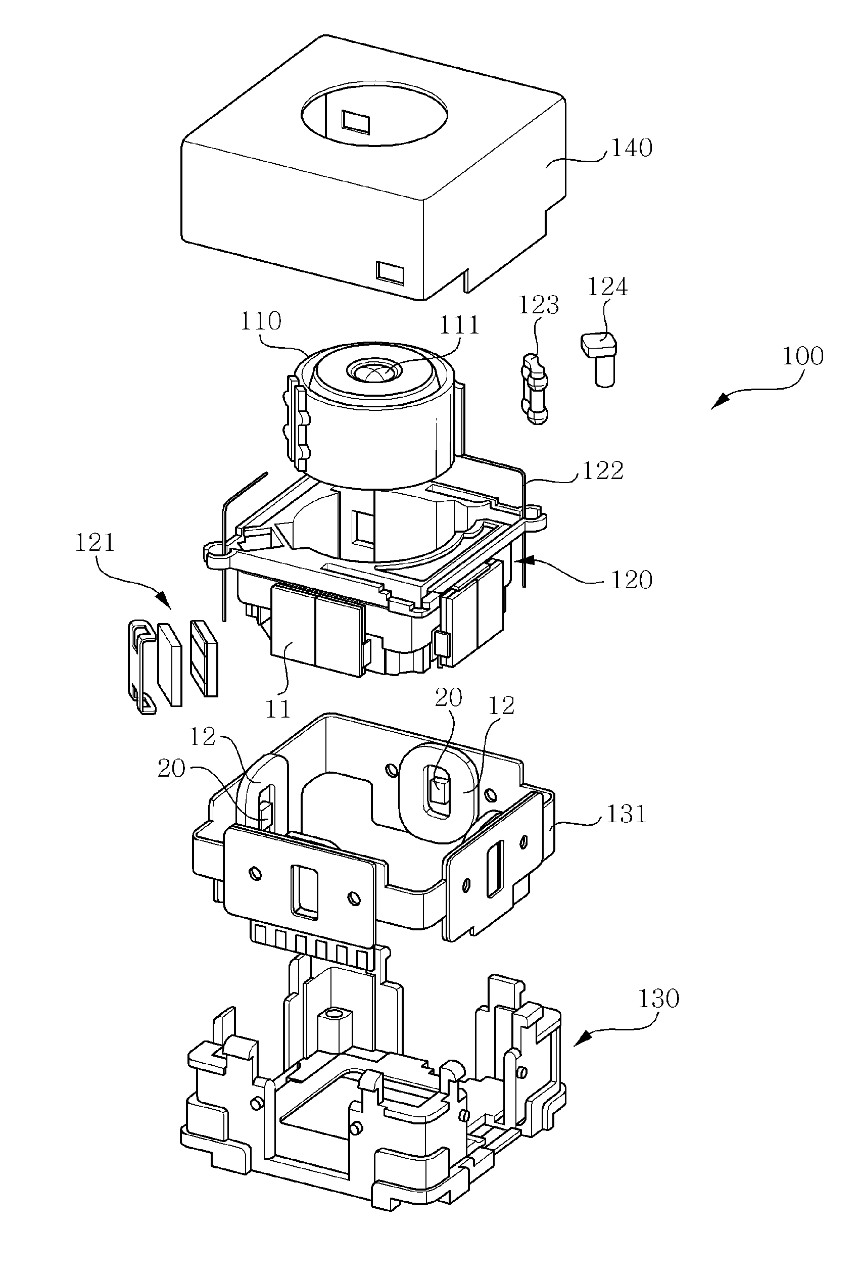
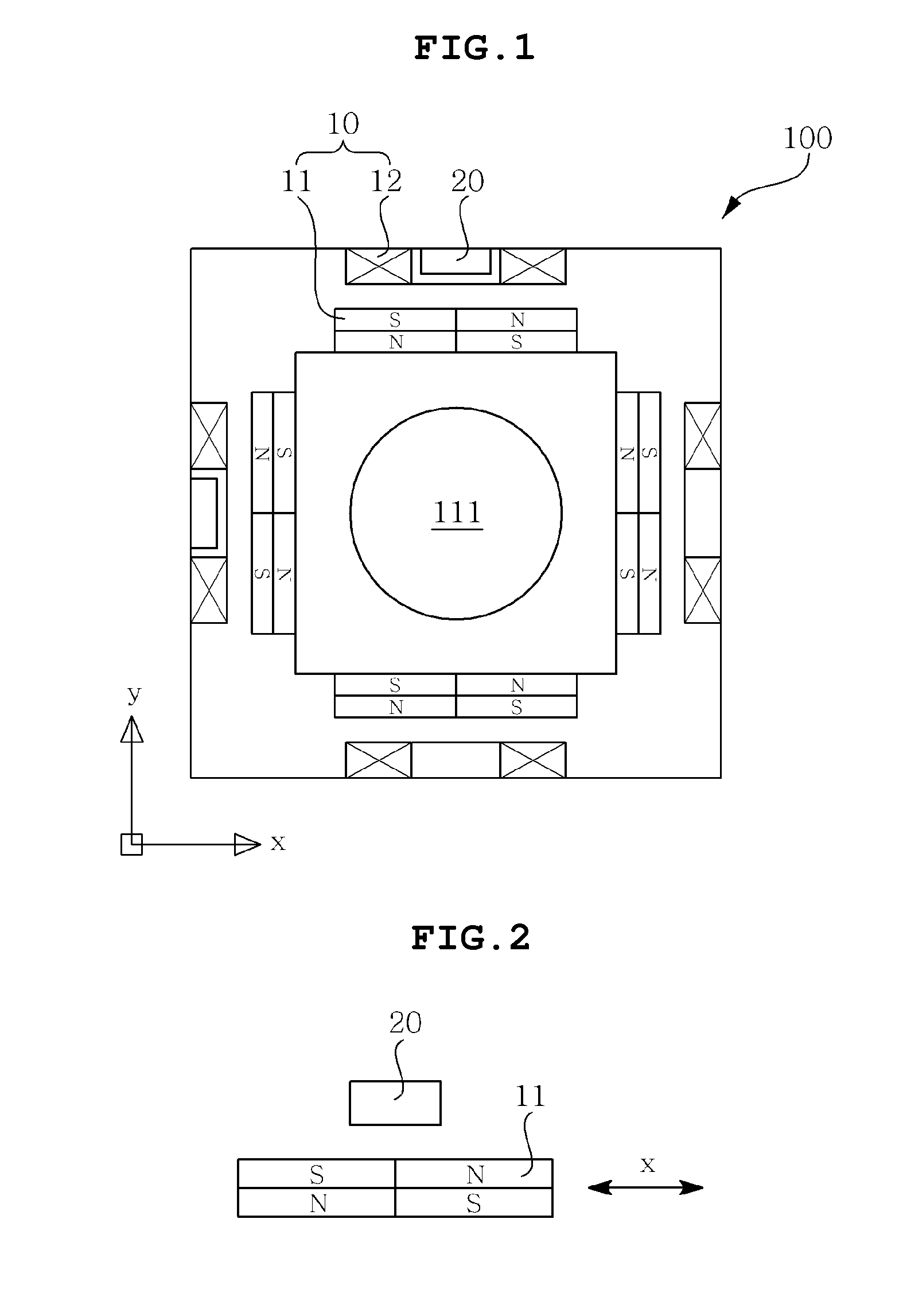
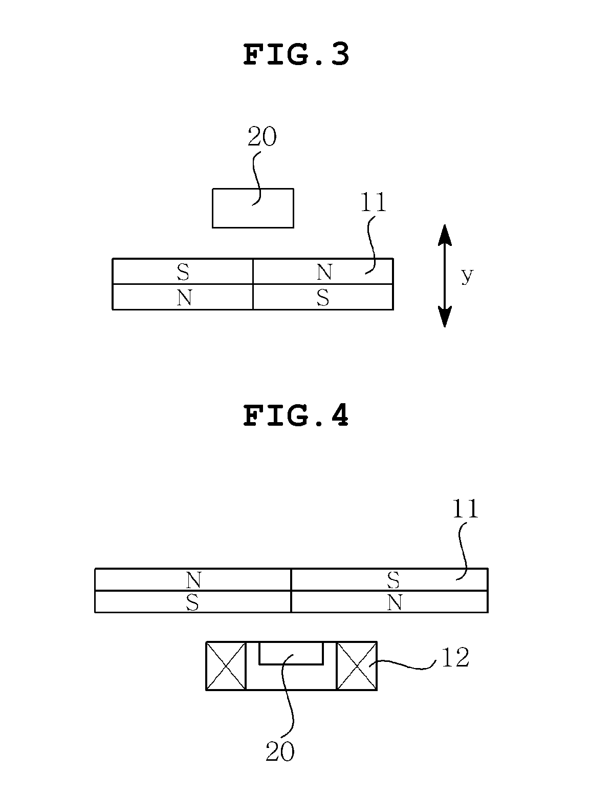
[0043]An optical image stabilizer (OIS) according to an exemplary embodiment of the present invention includes a drive unit 10, which includes magnets 11 disposed along the optical axis (z axis) of a camera module 100, and Hall sensors 20, one face of each of which is opposed to a corresponding face of the magnets 11.

[0044]Each Hall sensor 20 generates a variation in a signal in response t...


PUM

PropertyMeasurementUnit
opticalaaaaaaaaaa
displacementaaaaaaaaaa
Hallaaaaaaaaaa

Abstract

An optical image stabilizer, in which a magnet and a coil are arranges such that they oppose each other. The Hall sensor is arranged such that one face thereof is opposed to one face of the magnet. The Hall sensor can easily detect the location of a group of lenses by generating a corresponding signal in response to a variation in magnetic force following a variation in the gap between magnets depending on the direction in which a group of lenses is driven, and simultaneously, in response to a variation in magnetic force that occurs when the group of lenses is displaced in the direction that intersects the direction of the gap.

Description

CROSS REFERENCE TO RELATED ED APPLICATION[0001]This application is a continuation of U.S. patent application Ser. No. 13 / 572,803 filed Aug. 13, 2012, which claims the benefit of Korean Patent Application No. 10-2011-0140262, filed on Dec. 22, 2011, entitled “Hand Vibration Correction Device”, which is hereby incorporated by reference in its entirety into this application.BACKGROUND OF THE PRESENT INVENTION[0002]1. Technical Field[0003]The present invention relates, in general, to an optical image stabilizer.[0004]2. Description of the Related Art[0005]As camera modules are having higher-resolution pixels and higher functionality, they are being applied to a wider variety of applications including mobile devices, such as mobile phones, notebook computers and tablet PCs. At the same time, as such applications are becoming smaller and slimmer, camera modules are becoming smaller and slimmer.[0006]Furthermore, conventional autofocus (AF) camera modules are required to have only a group ...

Claims


Application Information

Patent Timeline
Patent Type & Authority Applications(United States)
IPC IPC(8): G01D5/14G02B27/64G02B7/08G03B3/10G03B5/00H01F7/02
CPCG02B27/646G03B5/00G01D5/142G02B7/08H01F7/0205G03B3/10H02K41/0356G03B2205/0015G03B2205/0053G03B30/00
Inventor LIM, SOO CHEOLKANG, BYUNG WOOOH, SANG MIN
Owner SAMSUNG ELECTRO MECHANICS CO LTD
Why Eureka
Try Eureka