Display Device

a technology of a display device and a display plate, which is applied in the direction of lighting and heating apparatus, electric lighting, instruments, etc., can solve the problems of uneven light, uneven light, uneven light, etc., and achieve the effect of reducing warps in optical sheets and improving light unevenness

Inactive Publication Date: 2016-01-07
SAKAI DISPLAY PROD
View PDF2 Cites 5 Cited by
  • Summary
  • Abstract
  • Description
  • Claims
  • Application Information

AI Technical Summary

Benefits of technology

[0008]To address this, Japanese Patent Application Laid-Open No. 2010-108897 discloses a display device in which an elastic member that holds an optical sheet i

Problems solved by technology

Such an optical sheet member is, however, expanded by, for example, heat from the light source, resulting in warps or wrinkles in the optical sheet member, which may cause unevenness in light to appear on the liquid-crystal panel.
Though the display device in Japanese Patent Application Laid-Open No. 2010-108897 as described above may suppress warps or wrinkles in the optical sheet, it is not possible to prevent unevenness in light caused by warps or wrinkles from occurring if they are once produced in an optical sheet.
Thus, even in the case where the heat generated from the light source causes warps or wrinkles in the optical sheet member, which results in unevenness in the light emitted from

Method used


Image

  • Display Device
  • Display Device
  • Display Device

Examples


embodiment 1

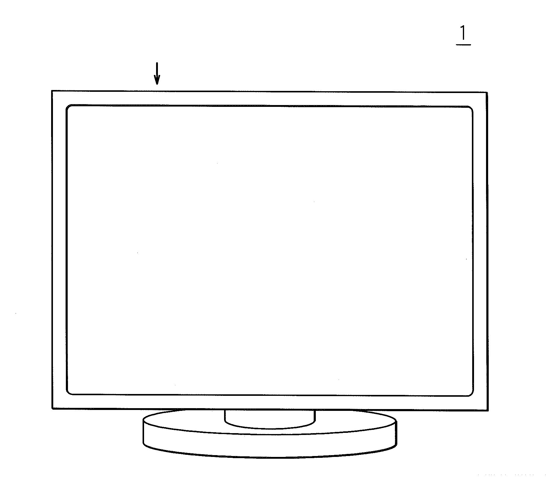
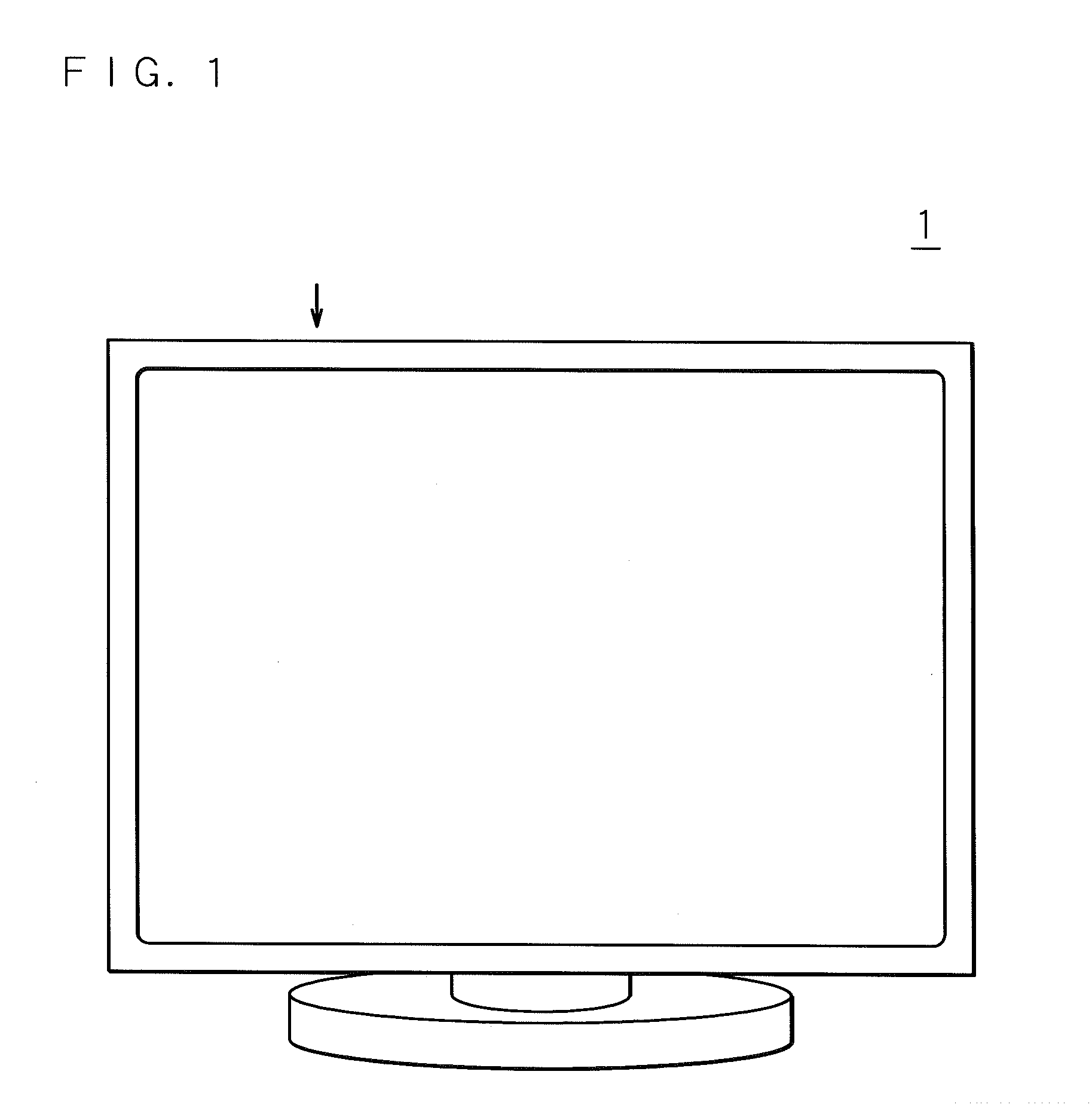
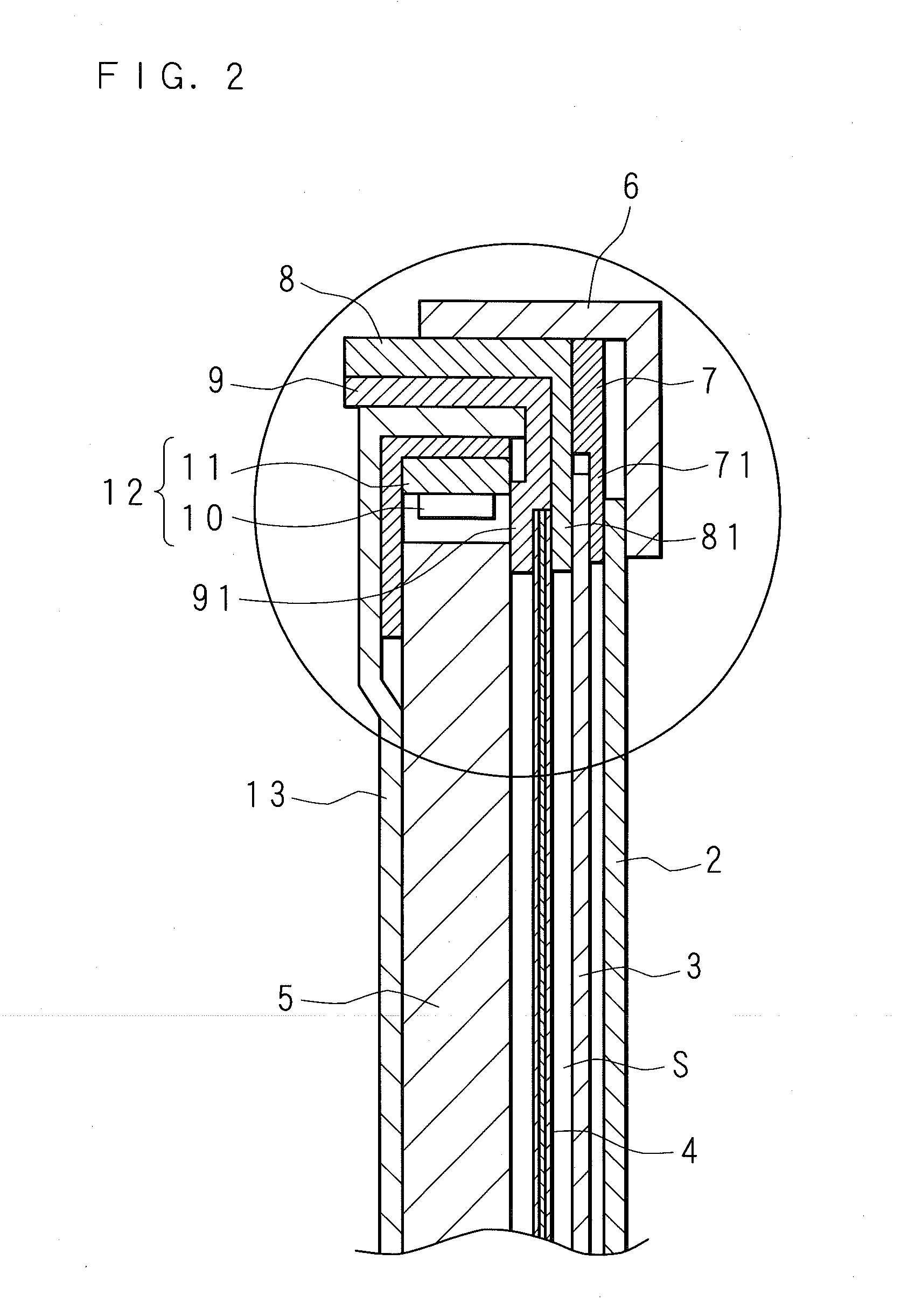
[0032]FIG. 1 is a front view of a liquid-crystal display device according to Embodiment 1 of the present invention, and FIG. 2 is a vertical cross sectional view of the main part of the liquid-crystal display device in the direction of the arrow shown in FIG. 1. FIG. 3 is an enlarged view of a circular portion in the vertical cross sectional view of the main part illustrated in FIG. 2. The reference numeral 1 in the drawings denotes the liquid-crystal display device according to the present invention. Moreover, for convenience of description, the up-down direction in the drawings is regarded as a vertical direction, whereas the left-right direction in the drawings is regarded as a horizontal direction.

[0033]A liquid-crystal display device 1 according to Embodiment 1 of the present invention, as illustrated in FIG. 1, includes a rectangular liquid-crystal panel 2 with one surface on its front side displaying an image. On the rear side of the liquid-crystal panel 2, an optical sheet m...

embodiment 2

[0054]The liquid-crystal display device 1 according to Embodiment 1 described an example where the optical sheet member 40 is a known material and is comprised of multiple optical sheets including the first diffusion sheet 41, the prism sheet 42 and the second diffusion sheet 43. The present invention is, however, not limited thereto.

[0055]Among the first diffusion sheet 41, the prism sheet 42 and the second diffusion sheet 43 constituting the optical sheet member 40 according to Embodiment 1, the prism sheet 42 (or micro lens sheet) is the one that is easily warped or wrinkled by thermal expansion in practice.

[0056]Accordingly, in the liquid-crystal display device 1 according to Embodiment 2, the optical sheet member 40 is constituted by the prism sheet 42 and a diffusion film 44. The structure of the liquid-crystal display device 1 according to Embodiment 2 will now be described below in detail.

[0057]FIG. 4 is a partial vertical cross sectional view of the main part of a liquid-cr...

embodiment 3

[0069]FIG. 5 is a partial vertical cross sectional view illustrating the configuration of the main part of a liquid-crystal display device 1 according to Embodiment 3 of the present invention.

[0070]In the liquid-crystal display device 1 according to Embodiment 3 of the present invention, as illustrated in FIG. 5, an optical sheet member 4 is located on the rear side of a rectangular liquid-crystal panel 2 having one surface at the front side on which an image is displayed, and a diffusion sheet 3 is provided between the liquid-crystal panel 2 and the optical sheet member 4.

[0071]Furthermore, in the other surface side of the optical sheet member 4, a light source 10 and a light guide plate 5 are located, the light source 10 and the light guide plate 5 being accommodated in a cabinet 13.

[0072]In the rear side of the liquid-crystal panel 2, a spacer 810 for supporting the liquid-crystal panel 2 is provided to be in contact with the circumferential part of the other surface of the liqui...


PUM


Abstract

Provided is a display device comprising a liquid-crystal panel and an optical sheet member including multiple stacked optical sheets emitting light from a light source toward the liquid-crystal panel, which can alleviate unevenness in light even in the case where, for example, light with such unevenness is emitted from the optical sheet member due to warps or wrinkles generated in the optical sheet member caused by heat generated by the light source.
A diffusion sheet is provided between a liquid-crystal panel and an optical sheet member with a gap from the optical sheet member. The light emitted through the optical sheet member is diffused by the diffusion sheet and gap, and then enters the liquid-crystal panel.

Description

[0001]This application is the national phase under 35 U.S.C. §371 of PCT International Application No. PCT / JP2014 / 051 922 which has an International filing date of Jan. 29, 2014 and designated the United States of America.BACKGROUND[0002]1. Technical Field[0003]The present invention relates to a display device including a liquid-crystal panel with one surface on which an image is displayed, and an optical sheet member disposed, opposite to another surface of the liquid-crystal panel and having multiple stacked optical sheets, to emit light from a light source toward the liquid-crystal panel.[0004]2. Description of Related Art[0005]In recent years, a display device having a liquid-crystal panel on which an image is displayed includes an optical sheet member which diffuses and condenses light from a light source to make the light uniform as it enters the liquid-crystal panel.[0006]The optical sheet member includes, for example, an optical sheet such as a prism sheet or a micro lens sh...

Claims


Application Information

Patent Timeline
IPC IPC(8): G02F1/1335G02F1/1339
CPCG02F1/1339G02F1/133504F21S2/00G02F1/133606G02F2201/54G02B6/0051G02B6/0053G02B6/0088G02B6/0001
Inventor YOSHIKAWA, TAKAHIRONAKAZAWA, TAKAYUKINEGORO, KAZUHIKOHORI, MAYUMI
Owner SAKAI DISPLAY PROD
Why Eureka
Try Eureka