System and method of controlling air blower for fuel cell vehicle

a fuel cell vehicle and air blower technology, applied in the direction of electrochemical generators, battery/cell propulsion, transportation and packaging, etc., can solve the problem of air blower overloaded, and achieve the effect of reducing increasing the maximum operation amount of the air blower, and sufficient air flow ra

Active Publication Date: 2016-01-07
HYUNDAI MOTOR CO LTD +1
View PDF4 Cites 13 Cited by
  • Summary
  • Abstract
  • Description
  • Claims
  • Application Information

AI Technical Summary

Benefits of technology

[0011]Accordingly, the present invention provides a system and method of controlling an air blower for a fuel cell vehicle to maintain a sufficient flow rate of air supplied to a fuel cell under any unfavorable driving conditions, such as vehicle's driving at a substantially high elevation and to improve stable operation of the air blower by accounting for systemic troubles, such as clogging of an air channel.
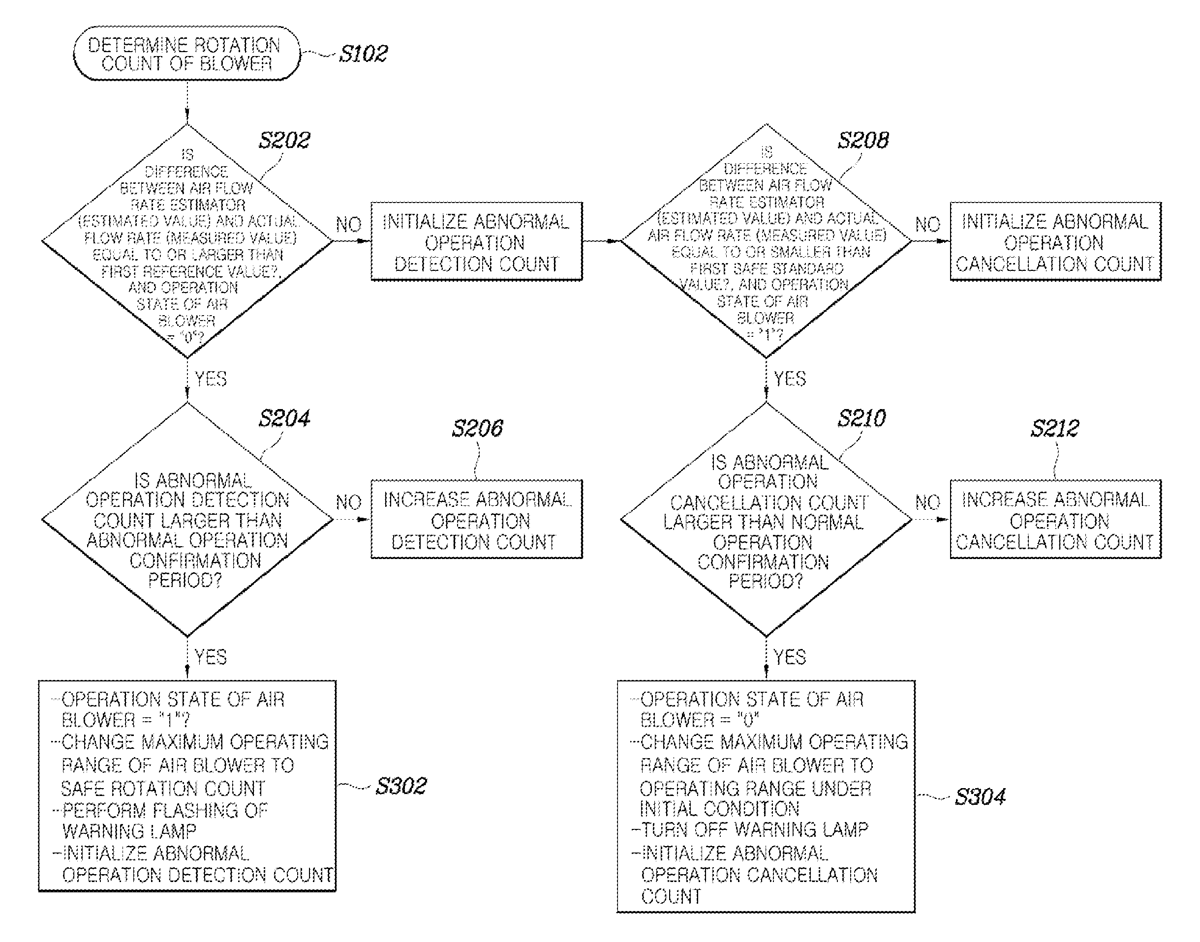
[0019]The method of controlling an air blower for a fuel cell vehicle having the structure described above may maintain a sufficient air flow rate by detecting conditions in which an air flow rate should be increased, such as driving at a substantially high elevation, and by increasing a maximum operation amount of the air blower according to the detected conditions. In addition, the structure of the present invention may prevent an abnormal operation of the air blower (e.g., operating under failure or causing failure) by detecting systemic troubles such as clogging of an air channel and reducing the maximum operation amount of the air blower to prevent overload to the air blower. In other words, it may be possible to enhance durability of the air blower by maintaining a sufficient air flow rate even under unfavorable driving conditions, accounting for systemic troubles, and preventing overload to the air blower.

Problems solved by technology

When a conventional air blower is used and the operation amount of the air blower is continuously increased to maintain a sufficient air flow rate under conditions in which it is difficult to maintain a sufficient air flow rate, such as when a vehicle is being driven at a substantially high elevation at which atmospheric pressure is substantially low; or when an air channel is clogged by impurities, the air blower may be overloaded.

Method used


Image

  • System and method of controlling air blower for fuel cell vehicle
  • System and method of controlling air blower for fuel cell vehicle
  • System and method of controlling air blower for fuel cell vehicle

Examples


Embodiment Construction

[0028]It is understood that the term “vehicle” or “vehicular” or other similar term as used herein is inclusive of motor vehicles in general such as passenger automobiles including sports utility vehicles (SUV), buses, trucks, various commercial vehicles, watercraft including a variety of boats and ships, aircraft, and the like, and includes hybrid vehicles, electric vehicles, plug-in hybrid electric vehicles, hydrogen powered vehicles and other alternative fuel vehicles (e.g. fuels derived from resources other than petroleum). As referred to herein, a hybrid vehicle is a vehicle that has two or more sources of power, for example both gasoline-powered and electric-powered vehicles.

[0029]Although exemplary embodiment is described as using a plurality of units to perform the exemplary process, it is understood that the exemplary processes may also be performed by one or plurality of modules. Additionally, it is understood that the term controller / control unit refers to a hardware devi...


PUM

PropertyMeasurementUnit
air flow rateaaaaaaaaaa
pressureaaaaaaaaaa
temperatureaaaaaaaaaa

Abstract

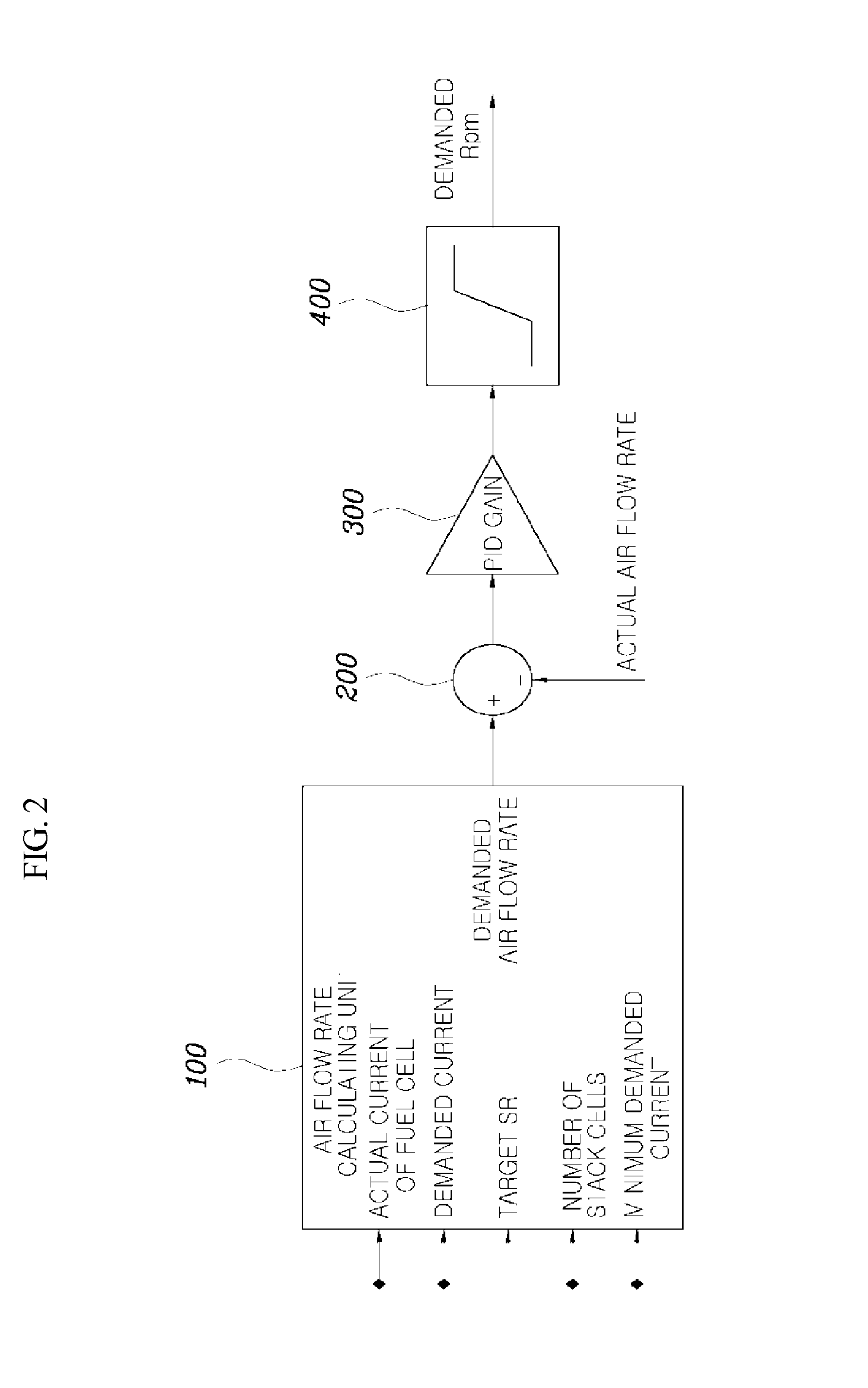
A system and method of controlling an air blower for a fuel cell vehicle are provided. The method includes determining an operation amount of an air blower to secure a sufficient air flow rate under present operating conditions and obtaining information regarding clogging of an air channel or information regarding a back pressure using the operation amount of the air blower. In addition, a maximum operating range of the air blower is changed based on whether a present state is an air channel-clogged state or a back pressure-increased state.

Description

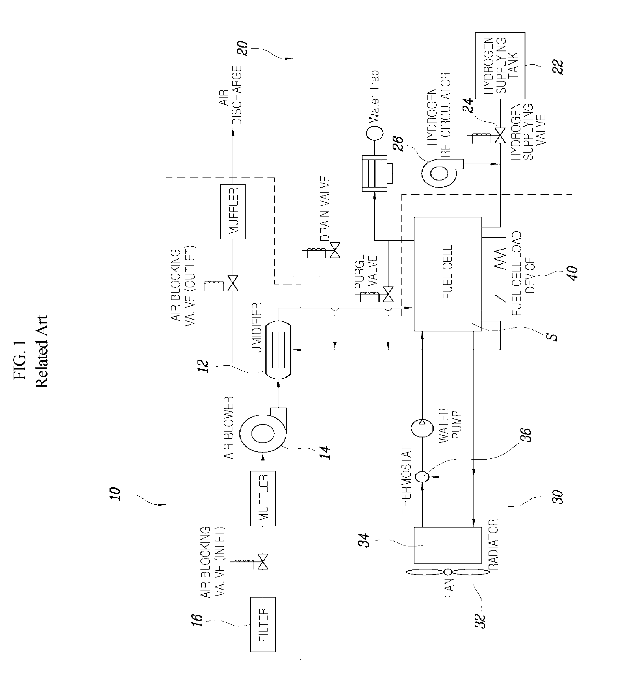
CROSS-REFERENCE TO RELATED APPLICATION[0001]The present application claims priority of Korean Patent Application Number 10-2014-0082452 filed on Jul. 2, 2014, the entire contents of which application are incorporated herein for all purposes by this reference.BACKGROUND[0002]1. Field of the Invention[0003]The present invention relates to a system and method of controlling an air blower for a fuel cell vehicle that prevents an abnormal operation of the air blower and maintains a sufficient air flow rate according to extraneous air conditions.[0004]2. Description of the Related Art[0005]A fuel cell stack of a fuel cell system produces electricity through an electrochemical reaction of oxygen supplied in the form of air, and hydrogen, which is supplied as fuel, so that the resulting electricity can be used as energy for driving a vehicle. As illustrated in FIG. 1, a fuel cell vehicle includes a fuel cell stack which produces electricity in the fuel cell stack. The fuel cell vehicle also...

Claims


Application Information

Patent Timeline
Patent Type & Authority Applications(United States)
IPC IPC(8): H01M8/04
CPCH01M8/04104H01M8/04992H01M8/04753H01M8/04664H01M2250/20Y02E60/50Y02T10/70Y02T90/40B60L50/50H01M8/04
Inventor KWON, SANG UKLEE, NAM WOOLEE, HEON JOONG
Owner HYUNDAI MOTOR CO LTD
Why Eureka
Try Eureka