
Anchoring Clamp on Bundle Wires for High-Voltage Electric Lines and Dampening Spacer Provided with Such Clamp

Active Publication Date: 2016-01-07
A SALVI & C SPA
View PDF3 Cites 6 Cited by
  • Summary
  • Abstract
  • Description
  • Claims
  • Application Information

AI Technical Summary

Benefits of technology

The proposed spacer clamp has a simple tightening system that doesn't require experienced staff. It also eliminates the limitations of traditional bolt tightening by using an "on / off" system that remains constant over time. To account for potential changes in the fastening, Belleville washers are used as energy storage to accumulate force and make adjustments automatically.

Problems solved by technology

However, it is a solution which, on the one hand, offers a useless advantage, due to the fact that the opportunity of adjusting the tightening is not normally required, since the spacer clamps must all be tightened at a torque preset in the designing phase and, on the other hand, even thinking that the mounting and tightening work must be carried out on the building site, has a plurality of drawbacks, among which the need to employ special dynamometric wrenches.
A loosening of the grip on the wire may be caused by a number of possible variables, some of them connected to human error, others caused by unforeseeable and inevitable phenomena.
The causes can be:poor mounting or assemblyingpoor designunscrewingoscillations due to sub-span / Aeolian vibrationswire sliding / ageingthe accidental entry of dirt between nuts and bolts alters the tightening torque and increases the chances of loosening of the tightening, which may lead to wear / collapse of the wire.
The effects of these causes may be:premature failure of the dampening spacerunforeseeable vibration mode, due to the modified structureincrease of the width / stress on the wirecostly line maintenance
Moreover, the work is—by its nature and due to the mentioned critical work conditions—particularly long, delicate and difficult, also because the operator must bring into coupling separate pieces; even in the case in which the two parts of each clamp are pre-assembled with the corresponding bolts, when they must be fastened on the wire running along the line, the operator must firstly separate and then reassemble these parts on the wire, before tightening them one on top of the other.
Finally, precisely these difficult working conditions inevitably carry the risk of a non fully even tightening on all the wires of the electric line, and it is virtually impossible to check the correctness of the work carried out on all anchoring clamps.

Method used


Image

  • Anchoring Clamp on Bundle Wires for High-Voltage Electric Lines and Dampening Spacer Provided with Such Clamp
  • Anchoring Clamp on Bundle Wires for High-Voltage Electric Lines and Dampening Spacer Provided with Such Clamp
  • Anchoring Clamp on Bundle Wires for High-Voltage Electric Lines and Dampening Spacer Provided with Such Clamp

Examples


Embodiment Construction

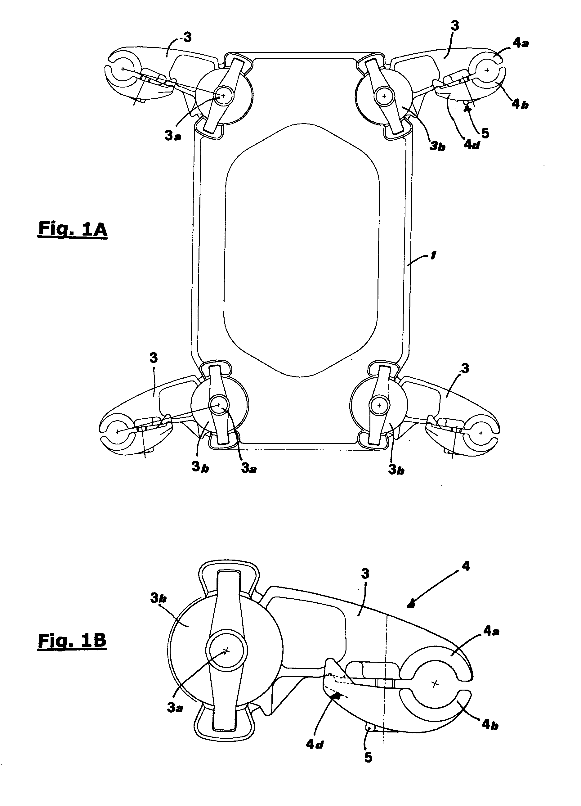
[0048]FIGS. 1A and 1B show, in an elevation view, a dampening spacer according to the prior art. It is a spacer for 4-strand bundle, comprising a rigid central body 1, on which oscillating arms 3 are hinged, each one through a pin 3a and dampening means 3b (not shown in detail, being well-known) which accomplish a dampening of the oscillations induced on arms 3 by the action of the electric line wires.

[0049]FIG. 1B shows well the structure of clamp 4 tightening on the wire (not shown), which implies, for each one of arms 3, a pair of jaws, of which a first one, referred to as 4a, is integral with arm 3 and a second one, referred to as 4b, makes up a separate piece but mounted moving with respect to the first one. The two jaws 4a and 4b are associated by means of a bolt 5 and a guiding tooth 4d. This construction is anyhow well-known and no further explanation is deemed necessary here.

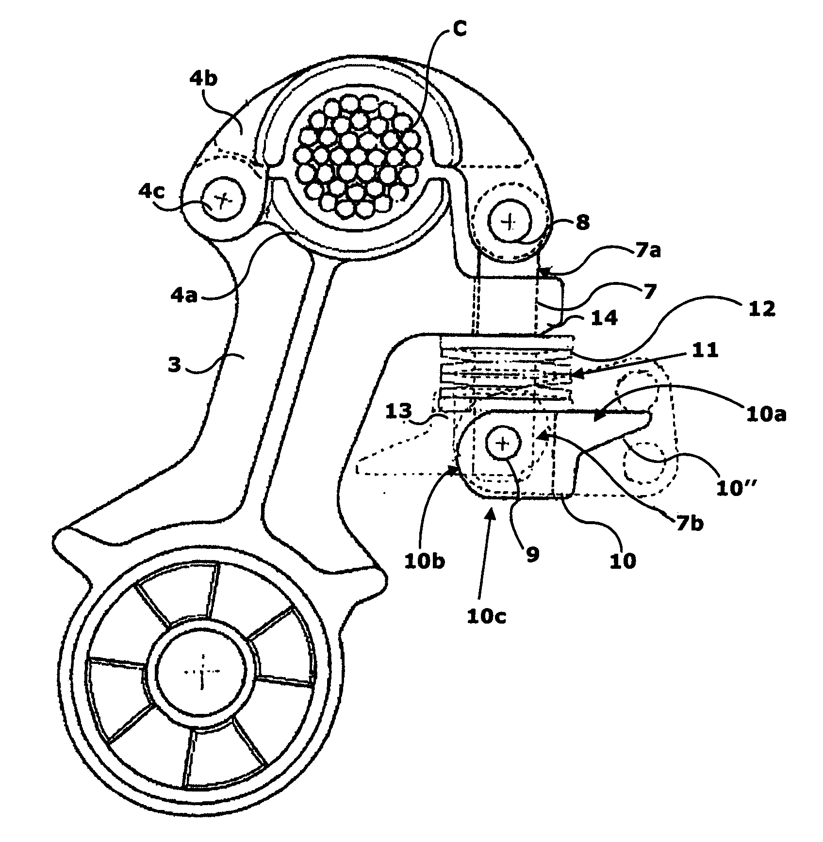
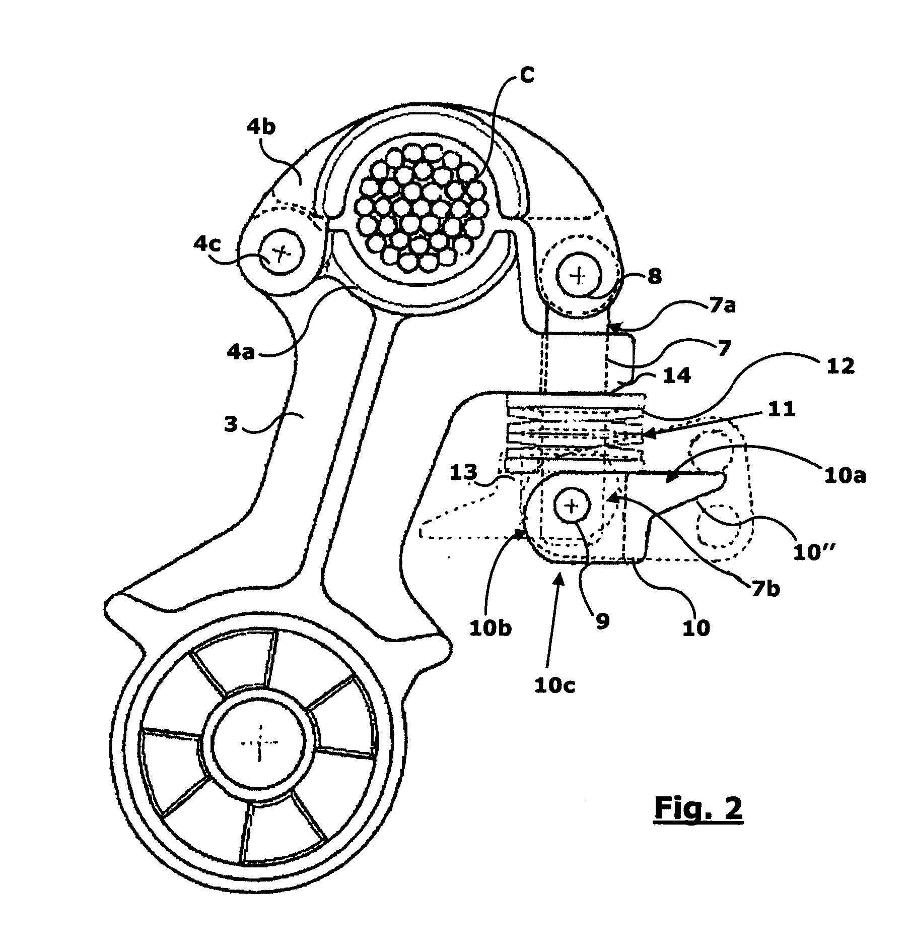
[0050]FIG. 2 and following ones show instead the configuration according to the invention. Oscillati...


PUM


Abstract

The present invention relates to a clamp and a spacer for bundle-shaped wires of high-voltage electric lines, as well as a relative mounting kit. The clamp comprises an arm for fastening to wires, at the free end of which two fixed jaws are formed. The second jaw being movable through disengageable tightening means, both jaws being provided with opposite saddles for the housing of wire, wherein the second moving jaw has a first end mounted rotating on a pin, carried by said fastening arm in a position coinciding with a first end of the first jaw, while with a second end it is apt to cooperate with tightening means. The tightening means comprise a tie rod having an end mounted rotating on the jaw and a distal end constrained through a constraint pin to a cam lever.

Description

INVENTION BACKGROUND[0001]The present invention concerns the spacer sector and, specifically, the sector of dampening spacers for high-voltage electric lines and, more precisely, electric lines which use bundle wires. More precisely, the invention relates to the structure of the anchoring clamps by which said spacer is fastened to the wires of the bundle.STATE OF THE PRIOR ART[0002]As known, aerial electric lines represent by far the most used case of long-distance power lines. They comprise a plurality of wires stretched between support posts. Normally, especially for higher-voltage long-distance power lines, each line wire consists of a bundle of elementary cables or wires, because that allows to increase the transmissible power, limiting dispersions and interfering electromagnetic fields. The most commonly used bundles consist of two, three or four elementary cables.[0003]As known, the individual wires of the bundle must be kept at the correct mutual distance, along the entire sp...

Claims


Application Information

Patent Timeline
IPC IPC(8): H02G1/04H02G7/12H02G7/05
CPCH02G7/12H02G1/04H02G7/053H02G7/125
Inventor TUFARI, ALDO
Owner A SALVI & C SPA
Learn More