Dynamically-balanced folded-beam suspensions

Inactive Publication Date: 2016-01-07
TECHNION RES & DEV FOUND LTD
View PDF1 Cites 4 Cited by
  • Summary
  • Abstract
  • Description
  • Claims
  • Application Information

AI Technical Summary

Benefits of technology

[0009]It is shown in this disclosure that there is a fundamental problem with the design of prior art folded-beam suspensions, and that their dynamic response cannot be linear, even when very small vibration motions are considered. The geometrical nonlinearity is shown to be caused by inertial effects which induce axial stress in the beam flexures. Based on this assumption, a new method of constructing a dynamically-balanced folded-beam suspension is given, in which axial stresses are not induced. This is achieved by ma

Problems solved by technology

However, the dynamic response of such prior art folded beam suspensions is known to be linear only in a limited range of extremely small motion.
It has been believed up to now that such non-linearity is a result of large deflections or electrostatic forces, but no reliable method or structure has been devised to avoid this non-linearity.
However, the response of gap-closing electrostatic actuators is nonlinear and they suffer from pull-in instability.
Over the years much progress has been achieved in the design of gap-closing electrostatic resonators, but nonlinearities still affect their performance.
Folded-beam suspensions are designed to perform as linear springs, but it has been found that, unlike their static characteristic, their dynamic response is nonlinear.
This is a serious limitation since a non-linear response means that the resonant frequency of the system incorporating the folded beam suspension is not constant, but is dependent on the amplitude of the vibration.
This nonlinear response has been observed for many years, but the reason has not been fully understood.
However, other than a general statement that, because of the difference in thermal expansion rates, the long and

Method used


Image

  • Dynamically-balanced folded-beam suspensions
  • Dynamically-balanced folded-beam suspensions
  • Dynamically-balanced folded-beam suspensions

Examples


examples

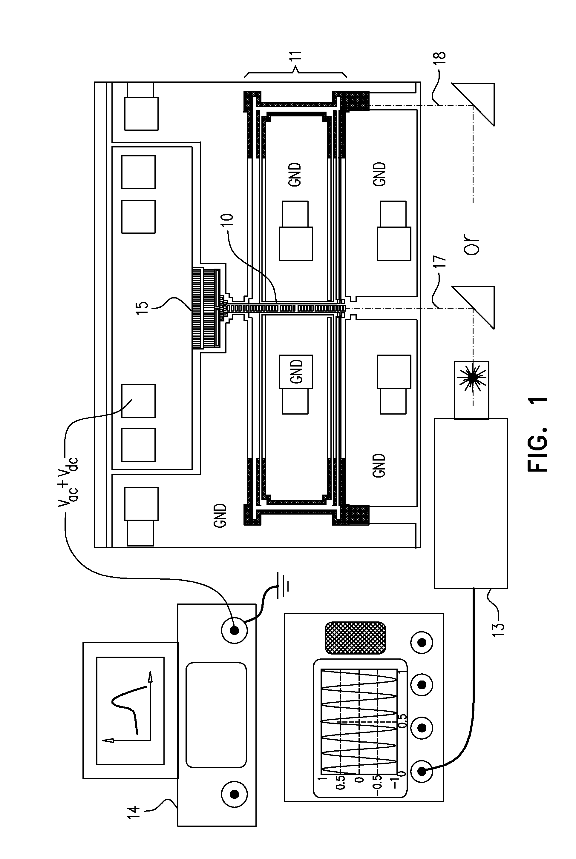
[0119]In order to verify the above mathematical calculations, test devices were fabricated using the SOIMUMPs technology described at the beginning of this disclosure. The test devices were electrostatic comb-drive resonators suspended on folded-beam suspensions. The devices were fabricated in a (100) single crystalline silicon layer, with flexure beams oriented in the (110) direction. Two types of test devices were fabricated: one device with a standard prior art folded-beam suspension with beams of equal length, and the other with a dynamically-balanced suspension of the present application, with a shortened anchored beam. The devices were designed with an arbitrary mass ratio of msh=mfb.

[0120]The flexure beams were designed to be h=3 μm wide, 1=25μm thick, and L2=600 μm long, except for the shorter beam in the dynamically-balanced suspension. For these devices the shorter beam is designed to be L1=497 μm long. This length was determined by solving equations (35) and (36), with th...


PUM


Abstract

It is believed that the folded-beam suspension responds as a linear spring. Though true for the static response, this is not true for dynamic responses. For shuttle displacements in the order of the width of the flexure beams, the response becomes strongly nonlinear. This nonlinearity is caused by axial stresses which are induced due mainly to the inertia of the flying bar. A solution for this problem is given by shortening the anchored beams of the suspension by a predetermined amount, such that the flexure beams between anchor and flying bar, and between flying bar and shuttle have different lengths. In this dynamically-balanced suspension, the ratio between the motions of the shuttle and of the flying-bar ensures that the effective shortening of all beams is the same. Therefore, no axial stresses are induced, and the motion ratio is constant and unaffected by motion amplitude, resulting in a linear dynamic spring response.

Description

FIELD OF THE INVENTION[0001]The present invention relates to the field of micro-electromechanical systems (MEMS), especially to the construction of folded beam suspensions such as are used for supporting electrostatic comb drives.BACKGROUND OF THE INVENTION[0002]Folded-beams are prevalent as suspensions that support electrostatic comb-drives, which are intended to perform as linear springs over a wide range of motions. However, the dynamic response of such prior art folded beam suspensions is known to be linear only in a limited range of extremely small motion. It has been believed up to now that such non-linearity is a result of large deflections or electrostatic forces, but no reliable method or structure has been devised to avoid this non-linearity.[0003]Electrostatic MEMS resonators were first introduced in 1967, and have since found many applications. In the initial work by H. C. Nathanson et al on “The Resonant Gate Transistor,” published in IEEE Transactions on Electron Devic...

Claims


Application Information

Patent Timeline
IPC IPC(8): H02N1/00
CPCH02N1/008B81B2203/0163B81B3/0072B81B2201/0271B81B2203/0109H03H9/02362H03H9/02433H03H2009/0248
Inventor ELATA, DAVIDSHMULEVICH, SHAI
Owner TECHNION RES & DEV FOUND LTD
Why Eureka
Try Eureka